Composite horns
Contents
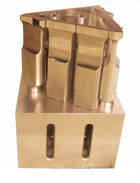
A composite horn is a full-wave horn consisting of at least two tip horns driven by a mother horn. A composite horn is used where normal horns are not feasible — where high welding amplitude must be concentrated at widely spaced locations or when a deep relief is needed.
|
|
|
Design guidelines
The following are some design guidelines.
- Specify the mother horn. The mother horn should have good performance when operated alone (i.e., uniform face axial amplitude, minimum transverse amplitude, good frequency separation between the axial resonance and secondary resonances, and acceptable life). The choice of optimum mother horn will depend on the frequency, shape, and size. Since these factors interact, some trial-and-error evaluation may be needed.
- Frequency. For a given mother horn size, a lower frequency will often give better performance since the ratio of half-wavelength to lateral dimension is larger. For example, assume the mother horn material is aluminum for which the wave speed is approximately 5000 m/sec. Then at 20 kHz the half-wavelength would be 125 mm whereas at 15 kHz the half-wavelength would be 167 mm. If the assumed mother horn size is 150 mm x 150 mm (regardless of the frequency) then the ratio of half-wavelength to lateral dimension would be 0.83 at 20 kHz versus 1.11 at 15 kHz.
(The above discussion is a generalization and is not always true. Again, some trial-and-error evaluation may be needed.) - Shape. Both cylindrical and block horns should be considered. For example, if the tip horns form a circular pattern then a cylindrical mother horn might be the first thought; however, a similar block horn might actually have better performance.
- Size. The optimal mother horn size may need to be somewhat larger than the pattern of the tip horns. For example, the tip horns might be confined to a 130 mm x 130 mm area. However, a 150 mm x 150 mm mother horn might give better performance than a 130 mm x 130 mm mother horn.
- Frequency. For a given mother horn size, a lower frequency will often give better performance since the ratio of half-wavelength to lateral dimension is larger. For example, assume the mother horn material is aluminum for which the wave speed is approximately 5000 m/sec. Then at 20 kHz the half-wavelength would be 125 mm whereas at 15 kHz the half-wavelength would be 167 mm. If the assumed mother horn size is 150 mm x 150 mm (regardless of the frequency) then the ratio of half-wavelength to lateral dimension would be 0.83 at 20 kHz versus 1.11 at 15 kHz.
- Specify the mother horn material. If the stresses are sufficiently low then larger mother horns should be aluminum. This will reduce material and machining costs and reduce starting difficulties (because of reduced mass). It has been suggested that if the tip horns are steel then the mother horn should be titanium. (Steel tip horns might be considered because of potential wear problems. However, titanium tip horns with replaceable tips or carbide faces might be used instead.)
- Consider the pattern of the tip horns. The tip horns should be positioned so that they are relatively balanced on the face of the mother horn. This may require using a somewhat larger mother horn than normal.
The pattern of the tip horns may need to be shifted or rotated slightly so tha the studs preferably do not intersect slots in the mother horn which could cause fatigue failures in the mother horn. Alternately, the slot locations in the mother horn can be adjusted if this would not significantly adversely affect the performance.
If the active tip horns can't be arranged in a relatively balanced pattern then dummy (inactive) tip horns may be needed in order to compensate. These horns can have any suitable shape as long as they don't interfere with other tip horns or with the plastic part. - Specify the tip horn material. Tip horns are often made of titanium but this will depend on the application.
- Specify the joint contact diameter. Regardless of the size of the tip horns, a small contact pad (machined washer) on the tip horn's stud surface may give optimum results. For example, on one 20 kHz composite horn a 20 mm diameter contact pad was used. By decreasing the contact area, a small contact pad can reduce the transverse motion of the tip horns, thereby reducing losses and joint problems. The contact pad should particularly be used if the tip horns are bar horns. (See the bar horns of figures 1 and 4.) The height of the contact pad only needs to be sufficient to accommodate subsequent material removal during reconditioning. For example, 1 mm height (or even less) should be sufficient.
- Choose the tip horn shape. Whenever possible, the tip horns should be cylindrical or flatted cylindrical so that they can be tightened without colliding with adjacent tip horns. Of course, this is not a problem if the spacing of the tip horns is large enough to avoid such interference.
- Tune the tip horns. All tip horns should be tuned very closely to the same frequency (within approximately ±10 Hz for a 20 kHz design). Otherwise, double-axial resonances may result (where some tip horns have high amplitude while others have low amplitude because they are not operating at the correct frequency).
- Tighten the tip horns.
- Number the tip horns. After assembly each of the tip horns should be numbered. The same number should be placed on the mother horn adjacent to the tip horn location. This will assist in reassembling if the tip horns must be removed for servicing (e.g., to dress the joint surfaces).
- Finished machining. In some cases some final machining must be done to the faces of the tip horns after assembly to the mother horn. However, because a tip horn is not well supported in this situation, it may chatter during machining and then may not properly fit the plastic part. To prevent this chatter the tip horns can be encased in a poured flexane cast prior to machining. This cast is then removed after all machining is complete.
Orienting the tip horns
Except in the case where the tip horns are axisymmetric (e.g., staking horns), each tip horn must be oriented so that its face is correctly positioned with respect to the plastic part. Because the tip horns are typically screwed to the horn face, their initial orientations will likely be incorrect.
Tip horns that can be freely rotated
Cylindrical tip horns and (usually) flatted-cylindrical horns can be freely rotated without interfering with other tip horns. For such horns the best method to adjust the orientation is to use a stud with a differential thread pitch (i.e., a stud with different thread pitches on each end). Differential threads are used in step studs; however, the step would not necessarily be required for the current use.
|
|
|
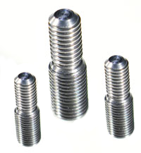
This method can be best illustrated with an example. Assume one end of the stud has a 1.25 mm pitch while the other end has a 1.5 mm pitch. Now assume that the 1.25 mm thread is in the tip horn while the 1.5 mm thread is in the mother horn. After the tip horn has been tightened to the mother horn, imagine that the stud is locked to the mother horn. Now the tip horn is loosened 1/4 turn (90° counterclockwise) so that a gap of 0.3125 mm (i.e., 1/4 x 1.25 mm) is created between the tip horn and the mother horn. The stud is then locked to the tip horn instead of the mother horn. Then when the tip horn is tightened the gap will be closed by using the 1.5 mm thread pitch in the mother horn. This will require a tightening rotation of 75° clockwise — i.e., (0.3125 mm / 1.5 mm) * 360°. Thus, the net reorientation of the tip horn would be 15° counterclockwise from its original position. The net reorientation of the tip horn can be calculated as —
\begin{align} \label{eq:10601a} \measuredangle_t = \measuredangle_s \left( 1 - \frac {p_t}{p_m}\right) \end{align}
where —
| \( p_t \) | = Pitch of thread in tip horn |
| \( p_m \) | = Pitch of thread in mother horn |
| \( \measuredangle_s \) | = Angle through which the stud is rotated relative to the tip horn |
| \( \measuredangle_t \) | = Net angle through which the tip horn is rotated relative to the mother horn |
The angles are positive when the rotation is counter clockwise (per the right hand rule). Thus, for the above example —
\begin{align} \label{eq:10602a} \measuredangle_t &= 90° \left( 1 - \frac {1.25~\textrm{mm}}{1.50~\textrm{mm}}\right) \\ &= 15° \nonumber \end{align}
If the angle of tip horn mis-orientation \( \measuredangle_t \) has been determined, then the required angle of stud rotation is —
\begin{align} \label{eq:10603a} \measuredangle_s = \large\frac {\measuredangle_t} {\left( 1 - \frac {p_t}{p_m}\right)} \end{align}
The actual process is different than in the above example.
- The stud is floated (not bottomed) in the tip horn to allow subsequent rotational adjustment of the tip horn.
- The stud is semi-secured in the tip horn to prevent it from rotating as the tip horn is tightened to the mother horn (e.g., with a medium thread locking compound, by distorting the stud threads prior to insertion, etc.).
- The tip horn is tightened to the mother horn. The angle by which the tip horn is mis-oriented is determined.
- The angle by which the stud must be rotated is calculated from equation \eqref{eq:10603a}.
- The stud is rotated.
- Repeat steps 3 through 5 until the tip horn is correctly oriented.
Note — Before using this procedure the tip horn should be torqued several times into the mother horn. This will seat the mother horn threads. Otherwise, if the threads have not been adequately seated then the tip horn will turn farther than expected after the stud adjustment.
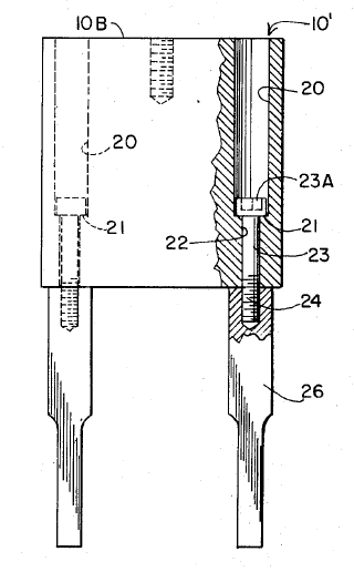
Alternately, the tip horn can be tightened with a bolt that is inserted in a counterbored hole in the back of the mother horn. This is one approach that was suggested by Davis[1] in his original patent (see figure 3). Although this allows quick orientation of the horn it can cause other problems such as heating under the bolt head.
|
|
|
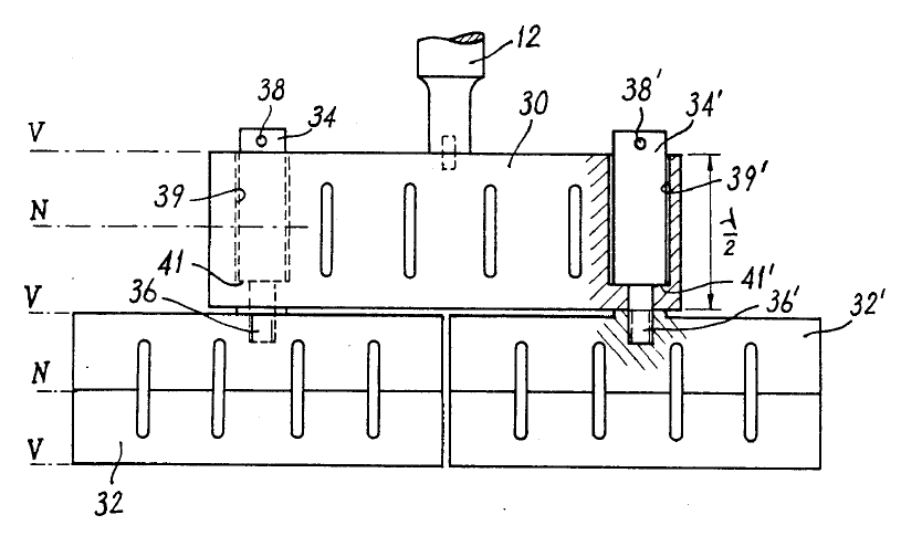
Scotto[2] proposed replacing the bolts with tuned half-wave rods with protruding studs (figure 4). However, this introduces other problems.
- Substantial counterbore machining of the mother horn is required to accommodate the rods.
- The material that is machined from the mother horn may unbalance the mother horn, thereby giving it undesirable face amplitudes.
- This may not be suitable for some slotted horns where the counterbores would intersect the slots.
- The rods may introduce additional undesired flexure modes.
|
|
|
Tip horns that are blocked from rotating
In some cases the tip horn design is such that it can't be rotated without colliding with adjacent horns. Then it can't be tightened by rotating. These are usually bar horns that sit close together. In this case the methods of Davis and Scotto (above) could be considered.