Tips (replaceable)
Contents
- Introduction
- Threaded attachment
- Clamped attachment
- Interference attachment
- Figures
- Tables
- Table 1. Standard 20 kHz flat-faced tips
Introduction
A replaceable tip is attached near the output end of a resonator. It may be useful in the following circumstances —
- Prototyping. In plastic spot welding or staking, the optimum contour of the horn face may not be known. Then prototype tips with different contours can be tried without the need to machine an entire custom horn.
- Wear. A horn's face will wear or deform due to abrasion, cavitation erosion, or impact. This wear causes frequency, amplitude, and application problems (see below). A solid one-piece horn would be expensive to replace after such wear. Instead, expendable tips may be used (see figures 1). However, if reliability is a high priority (e.g., for high volume applications, especially where downtime should be avoided) then a custom solid horn may prove more satisfactory. Then the horn's output surface could be coated with chrome, carbide, or titanium nitride for improved wear resistance. (Dukane[1], p. 6) However, these coatings may not be successful against cavitation erosion.
Tips can be divided into three categories depending on the method of attachment —
- Threaded
- Clamped
- Interference fit
Threaded attachment
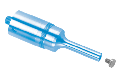
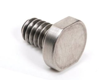
Threaded tips are secured to the resonator using an integral threaded stud. Figure 1 is an example.
|
||||||||||
|
|
Limitations
Materials
Dukane[2], p. 63 — "It is important to note that both the replaceable tips and the threaded horns must be made of titanium. No other materials should be used." Otherwise, this may lead to "heating" due to the "varying material density" (where the horn material is specified as titanium). (p. 105)
The reason for this restriction is unclear since it seems reasonable that horns and tips could also be made of steel. Also, the effect of intermixing materials (e.g., a titanium horn with a steel tip) is unclear but another report (unknown source) similarly states, "Tip and tool should not be of the same alloy, or there is a tendency for galling to occur." It should be noted that steel tips are routinely used with titanium metal welding horns, although the tip is secured with a nut rather than being threaded into the horn (figure 2). (See metal welding tips.)
Galvanic corrosion
For liquid processing applications, tips have generally been made of titanium which is relatively inert and also has relatively good resistance to cavitation erosion. Stainless steel tips would have similar advantages and might be preferable in certain circumstances. With a stainless steel tip and a titanium horn, there may be a concern for galvanic corrosion.
Serhan[1A] investigated galvanic corrosion of titanium-titanium joints and titanium-stainless steel joints for surgical implants. The titanium was Ti-6Al-4V; the stainless was 316 L. These materials were subjected to five million fretting cycles at 5 Hz in a saline solution. He concluded, "The results from this study suggest that galvanic corrosion does not play a significant role in mixed titanium alloy-stainelss steel spinal implant constructs." (p. 386) Hoi[1A] reached a similar conclusion for the interaction between commercially pure (cp) titanium and 316 L stainless steel.
Cavitation erosion
If cavication erosion is a problem then see here.
Weight and amplitude
Tips have limits on weight and amplitude in order to limit the inertial forces on the tip threads, horn threads, and tip-horn joint. The maximum tip diameter is typically limited to about Ø25 mm at 20 kHz. The smallest tips allow the highest amplitudes.
|
||||||||||||||||||||||||||||||||||||||||||||||||||||||||||||||||||||||||||||||||||||
|
Table notes —
- The mass are for flat-faced tips and includes the threaded shank. However, other tips (e.g., staking, spot welding) should also probably conform.
- References —
- Branson —
- Mass — Branson[7] (p. 24)
- Torques — Branson[3] (p. 2)
- Dukane[1], p. 11
- Qsonica[1] (p. 1) — The amplitudes specified by Qsonica are for liquid processing at 20 kHz. These amplitudes may be determined by the system's mechanical design (input amplitude to the horn and the horn's gain) rather than by performance requirements (tip heating, tip or horn fatigue, interface galling, etc.).
- Sonics & Materials[2] (p. 13)
- Branson —
Application forces
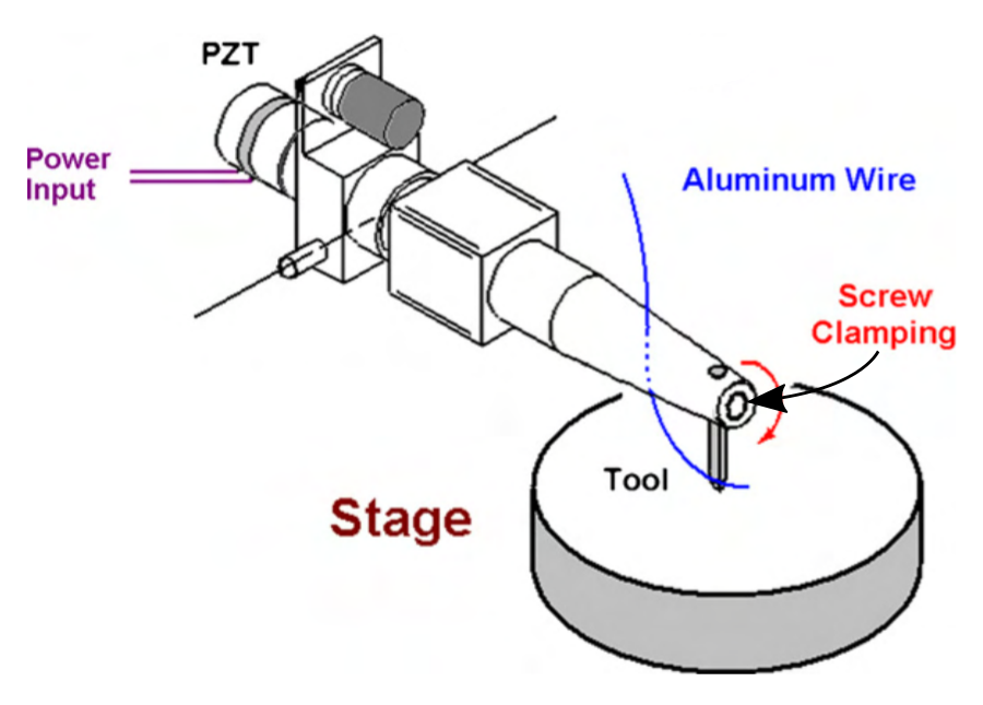
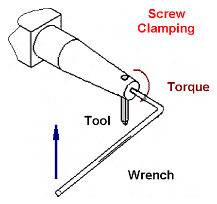
In addition to inertial forces, some tips will experience forces from the application. For example, metal welding places high shear forces on the tip (figure 2).
Use with organic solvents or low surface tension liquids
For the type of tip shown in figure 1, there seems to be a consensus that a replaceable tip should not be used if it will be submerged in organic solvents or low surface tension liquids. For example, Sonics & Materials[3] (p. 2) says, "Organic solvents (e.g., methylene chloride) or low surface tension liquids will penetrate the interface between the probe and the replaceable tip, thus carrying the particulates into the threaded section and isolating the tip from the probe. When processing samples containing organic solvents or low surface tension liquids, ALWAYS use a solid probe. NEVER use a probe with a replaceable tip."
Berliner Ultrasonics suggests that the problem with certain solvents is that they tend to wick under the tip-horn interface, thereby leading to cavitation erosion or wear by particulates in the fluid. Wicking supposedly occurs because the inertial forces on the tip during the contraction portion of the horn's stroke cause a small gap to open at the periphery of the tip-horn interface (i.e., the tip "flaps") whereby the fluid and particulates can enter. The problem is reportedly greater for large diameter tips.
Solutions
- Replace the tip with a solid half-wave or full-wave extension horn.
- Provide a shallow relief in the horn's face (next to the threaded hole) or tip's rear interface surface (next to the stud) so that the tip-horn contact occurs only at a small ring at the periphery of the tip-horn interface. This has two benefits —
- Because the interface contact area is reduced, a specified tightening torque will increase the interface contact pressure.
- With contact only at the interface periphery, flapping would be essentially eliminated.
- Use an O-ring at the horn-tip joint. Culp[0] has used this successfully for cavitation erosion tests of tips in molten solder.
Renewing replaceable tips
After significant wear has occurred, replaceable tips can sometimes be renewed by resurfacing the worn surfaces. The following should be considered.
- Frequency. When the eroded material is removed, the frequency of the ultrasonic stack will increase. Ultrasonic power supplies (generators) typically have a frequency band within which they will operate properly. This will depend on the design of the power supply. However, this frequency band is typically at least \( \pm \)1% of the nominal operating frequency (e.g., \( \pm \)200 Hz at 20 kHz) or more. The equipment manufacturer can provide the exact specification although the equipment may even operate properly outside the specified band. The tip can be repeatedly resurfaced until the frequency falls outside this band at which point the power supply should no longer start due to its internal protection circuitry.
- Amplitude. As the frequency increases, the output amplitude may change. If the amplitude is critical then it should be measured when the tip is new in order to establish a reference. Then when the renewed tip is installed the amplitude should be adjusted via the power supply to get the reference amplitude. These measurements can be taken in air.
- Heating. A new tip should be able to run for some time (at least 30 seconds) in air without appreciable heating of the tip. If a renewed tip produces appreciable heating then this means that too much material has been removed so the stiffness across the tip's surface is not adequate to support the tightening load. Then the renewed tip should be discarded.
To provide for extra wear, tips can initially be machined somewhat longer than normal. The frequency will then be below nominal (for instance 19.8 kHz instead of 20 kHz). However, the added weight will put additional stress on the tip-horn joint so this method should be avoided if any extra heating occurs at this joint.
Renewal interval (cavitation erosion)
If a flat-faced tip is subject to cavitation erosion then it should be renewed before the erosion becomes excessive. Otherwise, the tip's effectiveness will be reduced because of trapped bubbles within the cavitation cavities.
Sonics & Materials[4] (p. 16) recommends that the tip should be inspected for cavitation erosion every five to six hours and polished if necessary. Of course, this inspection/polishing interval will depend on the particular circumstances.
Assembly
Lubricants
Dukane[1] (p. 11) recommends —
- Apply a thin layer of Dow-Corning #4 high temperature, high pressure silicone grease (or #111 as an alternative) at the surface of the tip that mates to the horn.
- If a silicone-based grease can't be used then a petroleum-based grease can be used. However, it may leave carbonaceous deposits on the surface and require more frequent joint maintenance.
- Don't apply any grease to the tip threads.
The reason for the last recommendation is unknown. It may be because some lubricants may eventually foul the threads or cavitate the threads, thereby making the tip difficult to remove. However, there are dry lubricants (e.g., Teflon – PTFE) which would avoid this problem.
If the tip will come in contact with food products then the lubricant must be approved. In this case, a solid horn may be preferable to a horn with a replaceable tip.
Tightening torques
For the same tip, table 1 shows that Dukane recommends significantly higher tightening torques than Branson does. The reasons are not known.
General considerations
Thread loading direction
If a tip will be directly secured to the horn by a threaded fastener then the threads must be in the direction of horn vibration (e.g., see figures 1 and 2). This will place the threads in tension. If the threads are transverse to the direction of horn vibration then the threads will be placed in shear. In this case the inertial force and loading force on the tip will be too large for the threads to resist. This will allow the tip to slide at the tip-horn interface which will lead to heating there and likely fastener failure. (This recommendation may possibly be ignored if the amplitude is sufficiently small. In that case, however, a replaceable tip would seldom be needed to combat wear.)
Clamped attachment
In a clamped attachment, the tip is secured by a means that is external to the actual tip. For example, this may be means of a nut (figure 2), pinch clamp (figure X), set screw (figure 4), screws (figure 3), etc.
|
|
|
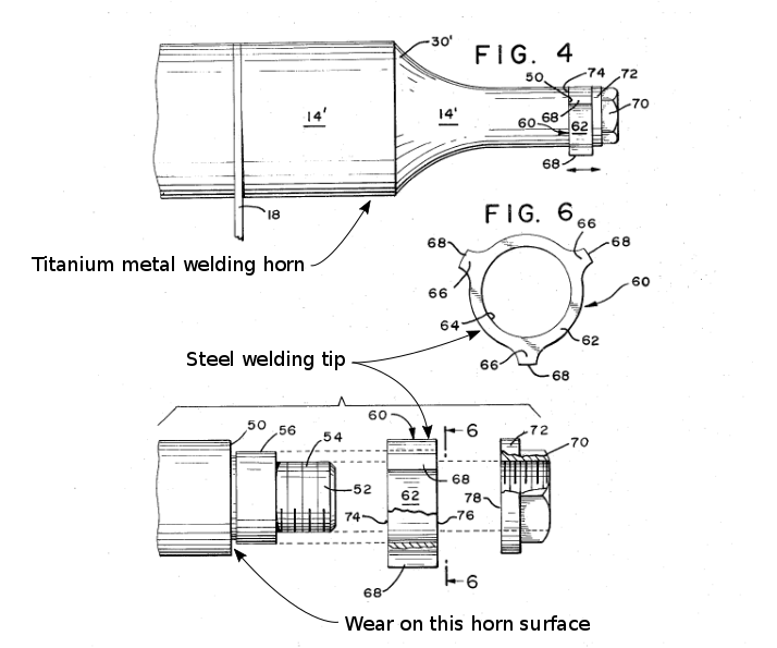
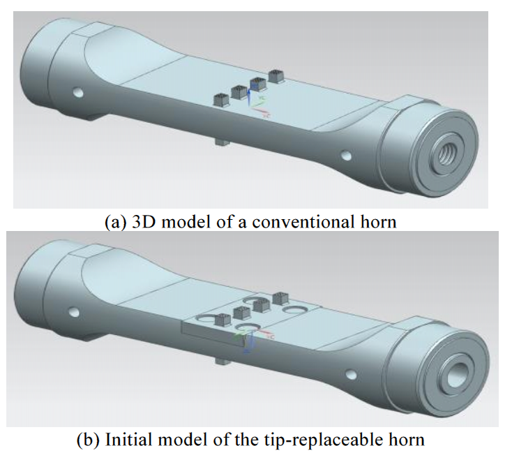
Figure 3b (Kim[1]) shows a proposed design for a metal welding horn where a replaceable tip (the central rectangular section) is secured by four transverse screws. Although FEA suggests that this design may be successful, it will undoubtedly fail in practice because of the transverse threads and, also, because the tip is large compared to the horn (resulting in high intertial load forces).
|
|
|
|
||||||||||
|
Interference attachment
An interference attachment can be achieved either by a locking taper fit or pressfit.
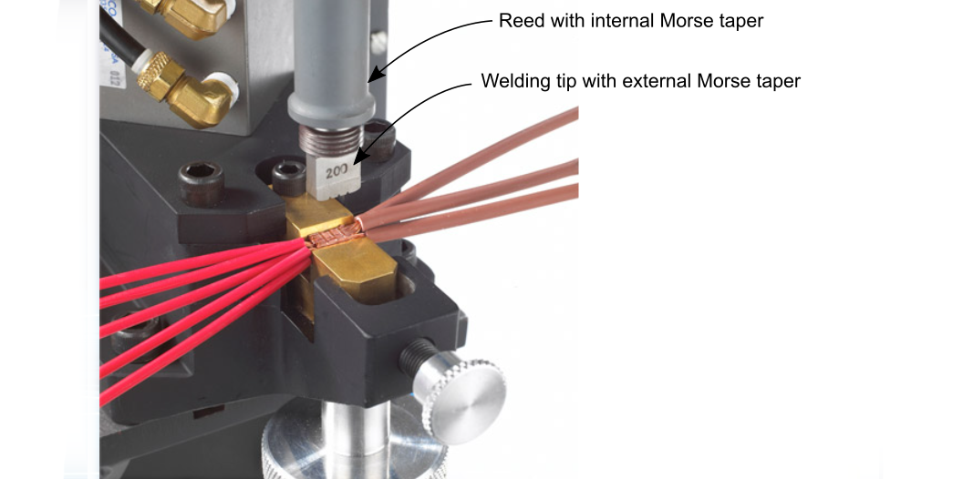
Sonobond's Wedge-Reed metal welder uses a tip with a shallow locking taper (Morse taper) which fits into a matching tapered bore in the free end of the vibrating reed (figure 5). The shown threads on the tip are not engaged with reed; instead they allow the tip to be removed via a jacking nut.
|
|
|
Culp[0] used a tapered pin as a welding tip in a lateral-drive metal welder. The tapered pin was inserted into a matching reamed hole in the horn. This design was somewhat successful but the joint ultimately degraded due to the high shearing forces during welding. This design was superceded by the replaceable tip of figure 2 which was more reliable and more versatile (allowing easy orientation with multiple welding lobes).