Appendix J: Comparison — short circuit resonance and open circuit resonance
Transducers are typically operated at (or near) either short circuit resonance or open circuit resonance. (Short circuit resonance is also known as series resonance or just resonance. Open circuit resonance is also known as parallel resonance or antiresonance.)
Amplitude
At short circuit resonance the impedance is relatively low so a small drive voltage can induce a large amplitude. If the drive voltage is held constant then the transducer's amplitude will rapidly collapse as the load increases. In this sense a short circuit resonance acts like a series wound motor where the speed is inversely proportional to the load.
In contrast, the impedance at open circuit resonance is relatively high so a large drive voltage is required to induce a reasonable amplitude. If the drive voltage is held constant then the transducer's amplitude will collapse only somewhat as the load increases (up to moderate loads). In this sense an open circuit resonance acts like a parallel wound motor where the speed is relatively constant regardless of the load.
Loss
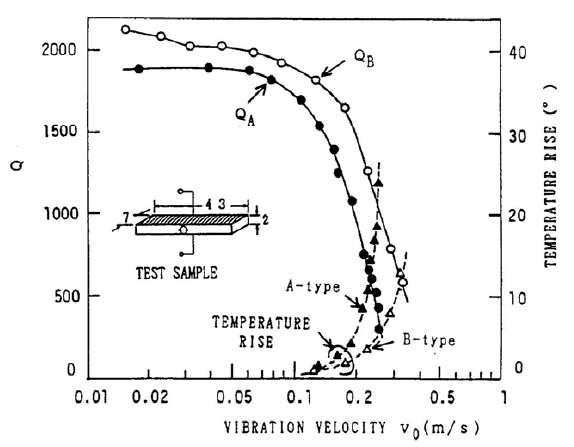
Hirose[1] considered the loss (Q) of a single piezoelectric ceramic that was driven longitudinally in the 31 mode. He discusses the causes of ceramic loss (section 3) and shows that (theoretically) antiresonant operation (parallel resonance) should have lower loss than resonant operation (series resonance). The experimental results in section 5 agree with this conclusion. In Hirose's figure 2 (figure J1 here), the quality factor \( Q_B \) for antiresonance is higher than \( Q_A \) for resonance, while the temperature rise (due to loss) for antiresonance is lower than for resonance. Note that the results are for a single ceramic that whose length is resonant in the 31 mode (i.e., the electric field is applied across the piezoceramic's thickness and the resulting vibration is along the piezoceramic's length). Presumably, the general conclusions are still valid for a non-resonant ceramic that is part of a transducer assembly.
|
|
|
Prokic[1] (p. 3.2-6) conducted power loading tests on Branson 20 kHz transducers. The power was measured in air with an attached bell horn and then as the bell horn was progressively immersed in water. The transducer amplitude was maintained constant at 20 microns peak-to-peak.
Under no-load conditions (i.e., in air) and up to moderate loading, these tests showed that open circuit resonance has lower loss than short circuit resonance. However, at heavier loading the reverse was true.
(It should be noted that Branson's transducers are designed to operate at open circuit resonance so the ceramic thickness and number of ceramics may not have been optimized for short circuit resonance. For example, since short circuit resonance requires lower drive voltage, fewer but thicker ceramics can be used without concern of electrical arcing.)
Power supply considerations
Compared to short circuit resonance, open circuit resonance has a very high impedance so that the current is typically low for a given power output. Mathieson[1] (p. 56) notes, "Driving under open circuit conditions can also be seen as advantageous, as the current consumption of the transducer is lower and therefore standard and relatively inexpensive power transformers can be utilized in the system design ..."
Q
If a device should malfunction and cause the user to become a ground path, the relatively lower current at open circuit resonance may reduce harm to the user.
Physical considerations
Parallel resonance --> high voltage ==>
- Ceramic thickness is limited by max allowed field strength
- Arcing -