Steel properties
Contents
- Figures
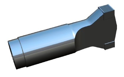
- Figure 1. Steel metal welding horn with integral welding surface
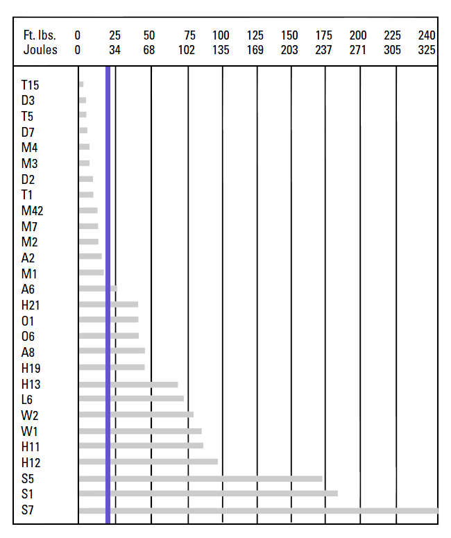
- Figure 2. Shock resistance comparison chart
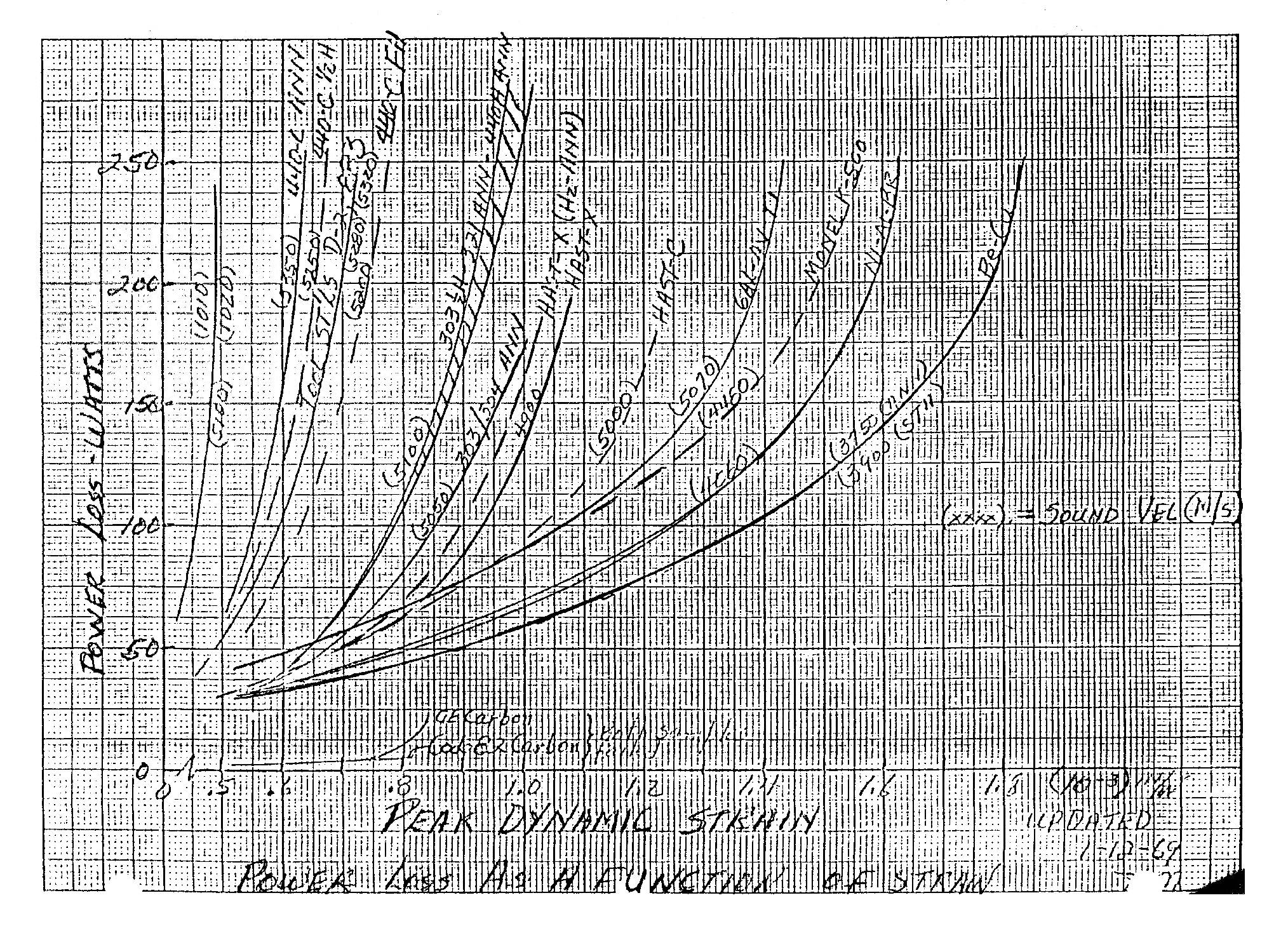
- Figure 3. Power loss of acoustic materials at 15 kHz
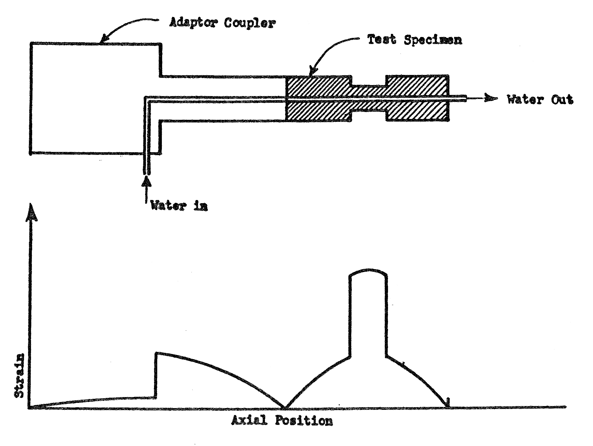
- Figure 4. Test setup to measure loss (Aeroprojects)
- Figure 5. Effect of grain size on internal friction Q-1
- Figure 6. Composition and treatment of test steels
- Figure 7. Effect of temperature on modulus of elasticity for various steels
- Figure 8. Effect of temperature on modulus of elasticity for various structural steels
- Figure 9. Tool steel machinability rating relative to W1 steel
- Figure 10. Comparative machinability of frequently used stainless steels and their free-machining counterparts
- Figure 11. Comparative toughness and wear resistance of CPM® steels
- Figure 12. Metal welding tests with CPM® horns
- Figure 13. 20 kHz rotary metal welding horn
- Figure 14. 20 kHz fatigue test specimens
- Figure 15. Ferro-Titinat WFN, CPM Rex M4, MC90 — 20 kHz fatigue test results
- Tables
- Table 1. Materials in figure 3
- Table 2. Details of figure 6
- Table 3. Effect of temperature on modulus of elasticity for various steels
- Table 4. Curve fit parameters for equation \eqref{eq:15301a}
- Table 5. Material properties of various steels
- Table 6. Loss measurements for various stainless steels
- Table 7. Machinability of CPM® V® materials
- Table 8. Machinability of CPM® Rex® materials
- Table 9. Properties of Ferro-Titanit WFN compared Rex M4 and MC90
Steels are used for ultrasonic resonators when wear resistance and/or impact resistance are required. For example, they have been used for metal welding horns (where the welding tip surface is integral to the horn — figure 1) and for horns that are used for insertion.
|
|
|
Material selection
Unlike titanium and aluminum, selecting an appropriate steel is complicated by several factors.
- There are thousands of different steels. Some have just slightly different alloy compositions but with big impact on performance.
- For heat-treatable steels there are many heat-treat variables that affect performance, for example the temperatures and durations (for preheating, heat treating, quenching, tempering), the surrounding media (air, inert gas, salts), etc. These may vary even for a specific steel, depending on the desired final properties.
- Although steels work well at relatively low strains, the loss can increase dramatically at higher strains (see figure 3 and table 1). Conventional (handbook) property listings don't specify loss properties because —
1) Loss isn't important for conventional (non-ultrasonic) applications.
2) Loss is not a fixed value but varies with the strain.
3) Loss depends on the heat treatment.
Instead, loss must be determined by actual ultrasonic tests at the expected strain levels for each material and heat treatment. Although low loss is important, other desired properties such as wear and notch sensitivity (e.g., for threads) must also be considered.
Fatigue
See a general discussion of fatigue. In addition, the following are specific to steel.
Notch sensitivity
A desirable property of acoustic materials is that they should have low fatigue notch sensitivity (i.e., the endurance strength with a notch should be be nearly equal to the same material without a notch). This is important, for example, in fatigue of threads.
Two similar tests that determine impact notch sensitivity are the Charpy and Izod. In these tests a heavy pendulum strikes and breaks a notched test specimen. The change in potential energy of the pendulum (before and after the strike) indicates the impact notch sensitivity. Figure 2 shows the impact shock resistance of various steels based on Charpy "V" notch test results. (Bryson[1], p. 139) Note — the vertical blue line has been added. It represents the Charpy "V" notch results for Ti-6Al-4V (annealed and STA sheet and bar). (See TIMET[1], figure 26, p. 18.) (Because titanium is orthotropic, its shock resistance depends on the test direction.)
|
|
|
Unfortunately, there may be little correlation between the impact notch sensitivity and fatigue notch sensitivity. As Yen[1] (p. 12) relates, "It is generally believed that hard steels are more notch-sensitive than soft steels either in a fatigue test, a static tension test, or an impact test. Some test data have indicated that the stronger the steel the lower is the Charpy impact value and the greater the fatigue notch-sensitivity; hence, one might infer the possibility of a relation between impact values and fatigue notch-sensitivity. However, no direct correlation between these two types of test has ever been reported and some contrary evidence indicating that there is no reason to expect a correlation has been presented".
Threads
Steel horns are known to fail in the threads.
Loss
Figure 3 shows the loss for a number of materials, including several steels. (This data, from Aeroprojects 1969, was conveyed to Culp[0] by Maropis[0].) The experimental setup is shown in figure 4. The loss was determined from the increase in temperature of water that flowed through the center of a highly stressed 15 kHz horn. Note that the losses are only valid for the particular frequency and sample shape. However, comparisons among the various materials are still valid. Table 1 shows the best determination of the hand-written notes from figure 3.
Notes —
- All steels are more lossy than Ti-6Al-4V and many are substantially more lossy.
- For 440-C steel, the wave speed decreases from 5350 m/sec to 5200 m/sec (-2.8%) as its condition changes from annealed to full hard. D2 exhibits a similar trend.
|
|
|
|
|||||||||||||||||||||||||||||||||||||||||||||||||||
|
|
|
|
Also see Loss measurements in stainless steel.
Effect of grain size
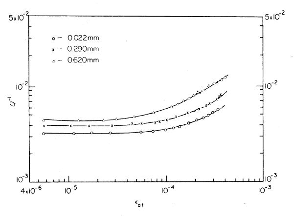
Puskar[1] tested a low carbon unalloyed steel at 23 kHz to determine the internal friction Q-1. (Note — loss varies directly with the internal friction which is the reciprocal of the quality factor Q.) The results are shown in figure 5 where the horizontal axis is the total strain amplitude \( \epsilon_{at} \). (It is believed that this is the peak strain rather than the peak-to-peak strain although this is not explicitly stated.)
As the grain size is reduced (likely due to the heat treatment process) the internal friction is also reduced. It is likely that there is some point at which further reduction in grain size does not result in further reduction in internal friction. However, this cannot be deduced from the given data.
Figure 5 also shows that, up to a certain critical strain \( \epsilon_{c} \), the internal friction Q-1 remains constant. Above this critical strain the internal friction begins to increase (i.e., the internal loss increases faster than the stored energy). It is desirable that \( \epsilon_{c} \) should be as large as possible so that a resonator can be vibrated at high amplitude without experiencing unexectedly high loss. Figure 5 shows that \( \epsilon_{c} \) is largest when the grain size is smallest. For example, for a grain size of 0.620 mm \( \epsilon_{c} \) is 7.3e-5 whereas for a grain size of 0.022 mm \( \epsilon_{c} \) increases to 1.3e-4.
Also, there is a critical strain \( \epsilon_{c} \) at which the internal friction starts to increase (i.e., the curves trend upward). This critical strain is the strain at which the internal loss increases faster than the stored energy.
\( \epsilon_{c} \) increases as the grain size decreases. For example, for a grain size of 0.620 mm \( \epsilon_{c} \) is 7.3e-5 whereas for a grain size of 0.022 mm \( \epsilon_{c} \) increases to 1.3e-4. Thus, considering only the effect of loss, this fine-grained material could be driven at substantially higher amplitudes than the same coarse-grained material. The same is likely true for other steels.
|
|
|
Temperature effects
Effect on modulus of elasticity (Young's modulus)
The modulus of elasticity of steel decreases with increasing temperature (i.e., the material is easier to compress). Thus, resonators that operate at elevated temperatures must have a shorter tuned length in order to maintain a compatible operating frequency.
Particular steels
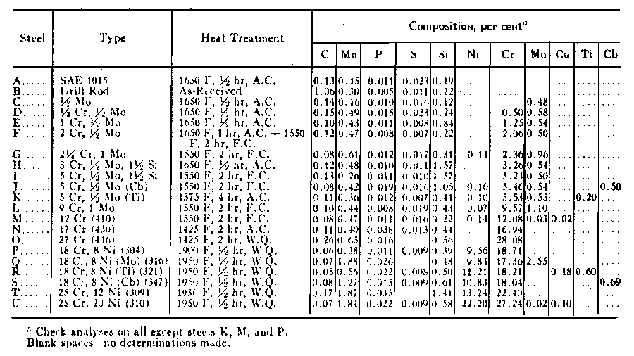
Garofalo[1] tested a series of steels to determine the relation between modulus of elasticity and temperature. Figure 6 shows the specifics of those steels.
|
|
|
|
||||||||||||||||||||
|
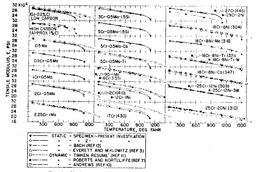
Figure 7 (Garofalo[1], p. 18) shows the results of Garofalo's tests together with test results from other sources.
|
|
|
Results (pp. 19-20) —
|
||||||||||||||||||
|
Note from figure 7 that the trends for many of the materials become nonlinear above about 900 °F (480 °C). The 300 series stainless steels often remain reasonably linear up to 1200 °F (650 °C) or higher.
Generic structural steels
Figure 8 (Seif[1], p. 9) shows the relation between modulus of elasticity and temperature for various "structural" steels from various testing sources (data sets). (See Seif[1] (p. 13) for more information.) Equation \eqref{eq:15301a} gives the associated least-squares regression curve fit, based on temperature data up to 725 °C.
Note the large data scatter in figure 8. Thus, figure 8 and equation \eqref{eq:15301a} should only be used if specific temperature data for the desired material are not otherwise available.
|
|
|
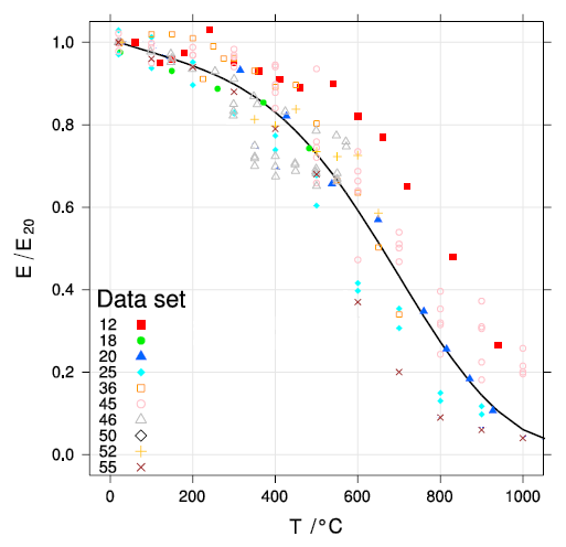
Figure notes —
- \( T \) is in °C.
- \( E_{20} \) is the modulus at 20 °C.
Regression equation for the curve of figure 8 —
\begin{align} \label{eq:15301a} \frac{E(T)}{E_{20}} &= \textsf{exp} \left\{ -\small\frac{1}{2} \left(\frac{T-20}{C_3}\right)^{C_1} \, -\small\frac{1}{2} \left(\frac{T-20}{C_4}\right)^{C_2} \right\} \end{align}
Equation notes —
- \( T \) is in °C.
- The equation constants are given in table 4. (See Seif[1], table 5‑2 (last four rows), p. 19. Note that fit constant \(C_2\) was forced to unity and was not fit (p. 11)).
Tabl 4. Curve fit parameters for equation \eqref{eq:15301a} Parameter Units Value \(C_1\) ——— 3.768 \(C_2\) ——— 1.000 \(C_3\) °C 639 \(C_4\) °C 1650
Effect on Poisson's ratio
Machinability
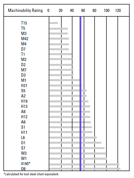
Figure 9 shows the machinability of various steels relative to W1 (a water hardening steel) at 100, where the machinability of W1 equals 40% on the AISI B1112 scale. (Bryson[1], p. 141. Note — the vertical blue line has been added. It represents the machinability of Ti-6Al-4V which is 22% on the AISI B1112 scale (Carpenter[1], p. 6) or 55% relative to W1.) Also see figure 10 for machinability of various stainless steels.
|
|
|
Known steels
The following steels have been used in some manner for ultrasonic resonators. The comparative merits of these steels are only partially known.
|
|||||||||||||||||||||||||||||||||||||||||||||||||||||||||||||||||||||||||||||||||||||||||||||||||||||||||
|
Table notes —
- HRC = hardness on the Rockwell C scale.
- The thin-wire wave speeds are calculated values.
- Bold type — Data that are measured or calculated from ultrasonic tests. Except as noted, these are from Culp[0]. Corresponding nominal "handbook" data (typically from manufacturer's data or matweb.com) are in parentheses.
- Unless otherwise stated, all properties are at room temperature.
Table references —
- FX Temper 2 tool steel —
Poisson's ratio was measured with tensile tests on three samples (25.4 mm square).
The density was measured in the laboratory.
- Young's modulus was measured with a 40 kHz ultrasonic full-wave/half-wave test (one sample). The test sample was Ø19.1 mm.
- Young's modulus was calibrated from FEA of a 40 kHz 2-slot bar horn (one sample each).
- Young's modulus was calibrated from FEA of a 40 kHz unslotted flatted-cylindrical horn.
- Al-Sarrif[1] — 20.8 kHz metal welding horn (FEA calibrated); 20 microns p-p (p. 68); 5 microns p-p input. The integrated welding tip was hardened to HRC 55-60 (p. 54); it is not known if this hardness applied only to the welding tip or to the entire horn.
- Stanasel[1] — 20 kHz metal welding horn (figure 1) for welding cables for the automotive industry, FEA analysis. Stanasel gives partial horn dimensions.
Notes for the following materials —
- Except as specifically recommended below, see Bryson[1] for suggested conventional heat treatments (without consideration of ultrasonic requirements). Consult the material manufacturer or your heat treater who may have additional recommendations.
- Unless otherwise stated, the "Characteristics" below are from the manufacturer's data or, alternately, from matweb.com.
- The listed applications are those which are known or available through the literature. The listed applications are not comprehensive and in many cases a particular material could easily be used for multiple applications. Also, some applications may be for prototype development where the chosen material may have been a matter of convenience, rather than an attempt for an optimal material.
Tool steels
AISI A2 tool steel
Characteristics — "High hardenability, high degree of dimensional stability in heat treatment, good wear resistance, fatigue life, toughness, and deep hardening qualities."
Applications — Ultrasonic processing of petroleum products. See Gunnerman's patent[2], paragraph 0013. (Note — The patent specifies "2‑A tooling steel". However, no such material could be identified. From the specified composition (paragraph 0013) the material is likely A2.)
AISI D2 tool steel
Characteristics — An air-hardening, high carbon, high chromium tool steel, heat treatable to HRC 60-62. It has excellent abrasion resistance due to a large volume of carbides in the microstructure.
Applications — Ultrasonic metal welding tips, plastics sealing horns, inserting horns.
AISI M2 tool steel
Characteristics — A tungsten-molybdenum high speed tool steel with excellent combination of wear resistance, toughness and hot hardness.
Applications — Ultrasonic metal welding horns and tips.
Suggested heat treatment for HRC 61-62 —
- With the part in the oven, preheat the oven in three steps for stress relieving.
- 620 °C (1150 °F) for 30 minutes
- 840 °C (1550 °F) for 15 minutes
- 1040 °C (1900 °F) for 15 minutes
- Hardening temperature — 1120-1180 °C (2050-2150 °F)
- Vacuum quench
- Double temper at 540-590 °C (1000-1100 °F). This will not reduce the hardness.
Vertex
Characteristics — "TLS Vertex tool steel is a versatile, high-chromium, air-hardening tool steel that is characterized by a relatively high attainable hardness and numerous, chromium-rich alloy carbides in the microstructure. These carbides provide good resistance to wear from sliding contact with other metals and abrasive materials. The primary alloy carbides in Vertex are smaller than the large chromium-rich alloy carbides which are characteristic of D2 tool steel. These smaller carbides result in better impact toughness and superior fatigue properties compared to D2.
The molybdenum addition in Vertex enhances the hardness of the alloy carbides, and more significantly, provides superior secondary hardening response compared to D2. Therefore, unlike D2, Vertex can be tempered at higher tempering temperatures yet still attain a hardness in excess of 60 Rockwell C. Because of the higher secondary hardness, Vertex exhibits superior wear resistance compared to D2 tempered at the higher tempering temperatures, as well as the superior toughness that is the result of the high-temperature tempering." (Vertex data sheet)
Originally manufactured by Timken Latrobe Steel; now Latrobe Specialty Steels Co.
Heat treatment (suggested by Latrobe). Final hardness should be ~HRC 56.
- Preheating. Preheat at a rate not exceeding 400 °F/hr (220 °C/hr) to 1150 - 1250 °F (621 -677 °C), equalize, then heat to 1400 - 1450 °F (760 - 788 °C).
- Austenitizing. Heat slowly from preheat. Furnace or Salt: austenitize at 1850 °F (1010 °C)
- Quenching. Air or pressurized gas. Cool to 150 - 125 °F (66 - 51 °C).
- Tempering. Temper immediately after quenching. Heat to 1050 °F (565 °C). Hold at temperature for 1 hour per inch of thickness (2 hours minimum), then air cool to ambient temperature and repeat.
FX Temper 2
Characteristics — "A moderate level of alloys nickel (Ni .80%), chromium (Cr 1.15%) and molybdenum (Mo .5%) provides this die steel with a good balance between fracture toughness and wear resistance at the widely used Temper 2 hardness (38-42 HRC)."
Manufactured by Finkl Steel. See data sheet.
Applications — Ultrasonic atomization of solder (Culp[0]).
Stainless steels
AISI 630 (17Cr-4Ni; 17-4 PH) stainless steel
PH refers to precipitation hardening.
Characteristics — A martensitic precipitation/age-hardening stainless steel offering high strength and hardness along with excellent corrosion resistance.
Applications — Ultrasonic dental tips.
AISI 304 stainless steel
Characteristics — Better corrosion resistance than Type 302. Resists most oxidizing acids and salt spray.
Applications — Sonochemistry.
Loss measurements
Table 6 shows loss measurements for several stainless steel materials (Culp[0]). Ony a single sample of each material was tested. Note that the loss for the 4xx series is significantly higher than the 3xx series even though the 4xx series has higher hardness (which is typically associated with lower loss). Also note that the 4xx series has no nickel content; it is not known if this contributes to its relatively high loss.
|
||||||||||||||||||||||||||||||||||||||||||
|
Table notes —
- Materials —
Only the most significant chemical components are listed. Other components may include manganese, molybdenum, phosphorous, silicon, and sulfur.
Inspection certificates with hardness values were provided.
Approximate equivalent HRC hardnesses are shown in ( ).
Ti-6Al-4V data are provided for comparison. - Horn dimensions —
Output diameter = 17.5 mm
Input diameter = 38.1 mm
Rear shoulder length = 25.4 mm
Transition radius = 38.1 mm
3/8-24 step stud (unbottomed) - Test equipment —
Frequencies — Branson A200A (low amplitudes)
Amplitudes —Fotonic Sensor
Power — Clarke-Hess watt meter (the loss includes that of the driving transducer)
Power supply — Sonics & Materials 600 watt Vibracell set at 40%
Transducer — same for all tests
Machinability
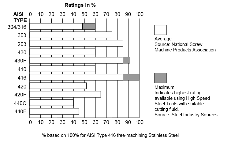
Figure 10 (Speciality Steel Industry of North America, p. 6) shows the machinability for various grades of stainless steel (higher values are better).
|
|
|
Cavitation erosion resistance
See here.
Powder metallurgy steels
CPM® tool steel
CPM® refers to the Crucible Particle [powder] Metallurgy process (Crucible Industries) with vanadium carbide between 10% and 18%. See Haswell[1] patent (1981).
V series
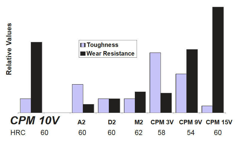
The V series differentiates based on the vanadium percent content. Figure 11 shows comparative performance. Note that the performance will change depending on the HRC hardness. However, for the specified hardness values both CPM 9V and CPM 10V are superior to D2 and M2. CPM 9V seems to have the best compromise of toughness and wear resistance.
|
|
|
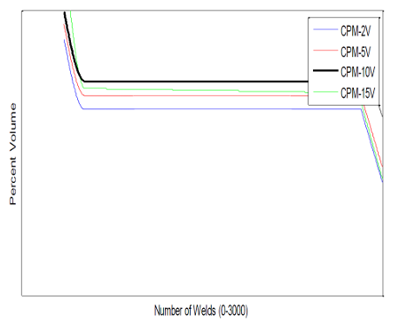
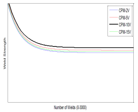
In ultrasonic welding of copper to aluminum test strips using horns made of CPM 2V, 5V, 10Vand 15V, Smith[1] found that CPM 10V had the least wear and also produced the highest weld strengths (figure 12). (The original research for these graphs does not seem to be available.)
|
||||||||||
|
Vieira[1] has patented a tire cutting horn that is made from powdered metal with a vanadium content between 9% and 15% (claims 11 and 12). Using CPM 10V the patent predicts that this horn should last three times longer than a titanium horn (paragraph 0027). The patent seems to suggest that the wear is improved, in part, by the higher thermal conductivity of the steel, although this is not entirely clear (paragraph 0027). The patent says that the hardness should be in the range of HRC 50-64 but should not exceed 64 because the material becomes brittle and tends to chip (paragraphs 0025 and 0026). The patent says that steel horns draw "meaningfully higher power" compared to titanium (paragraph 0005). However, this is not addressed elsewhere so it is not known if the powdered metal reduces this problem.
CPM® 9V®
Characteristics — A tool steel with 9% vanadium. It is a modification of CPM® 10V® with lower carbon and vanadium to improve toughness, although its wear resistance is somewhat lower. Its machinability is twice as good as CPM® 10V®.
Heat treatment — HRC 54-56 (suggested for best combination of toughness and wear resistance — see the data sheet). The data sheet notes, "Higher austenitizing temperatures can be used to obtain higher hardness, at a slight decrease in impact resistance. The lower austenitizing temperatures provide the best impact toughness." The data sheet also indicates that this material is suitable for nitriding.
Applications — Ultrasonic atomization of solder.
CPM® 10V®
Characteristics — A tool steel with 10% vanadium. It has high wear resistance and good toughness.
Heat treatment — HRC 60 (suggested for best combination of toughness and wear resistance — see data sheet). The data sheet notes, "Higher austenitizing temperatures can be used to obtain higher hardness, at a slight decrease in impact resistance. The lower austenitizing temperatures provide the best impact toughness." The data sheet also indicates that this material is suitable for nitriding.
Dukane[2] (p. 59) recommends HRC 52–56. However, Dukane notes, "Due to the hardness of the CPM10v horns, this causes them to be more brittle; thus, they are usually used for low amplitude applications. There are horn size limitations [unspecified] due to the brittleness." (Note — A brittle material does not have significant deformation beyond its yield point; chalk is an example. CPM 10V does not fit this definition and so is technically not brittle.)
"In the past, Dukane used D2 steel for this type of application [see §]. Working with metallurgists and through experimentation, we discovered CPM10V to be more reliable." (Dukane[2], p. 59) The criteria for reliability are not specified but may possibly be wear, fatigue resistance, or failure in the threads. (§ "severe wear, such as metal insertion, welding glass filled parts, and plunge cutting applications")
See Emmer[1A] for comparisons to 16MnCr5V steel and Ferro-Titanit at 30 kHz.
Applications — Ultrasonic tire cutting (Vieira[1] patent), metal welding (Lee[1], p. 2), metal insertion, welding glass filled parts, plunge cutting.
|
||||||
|
Rex® series
The Rex series has a high combination of vanadium, cobalt, and tungsten. These are high speed steels that are used in cutting tools.
Vieira[1] has patented a tire cutting horn that is made from powdered metal with combined vanadium, cobalt, and tungsten between 15% and 22% (claims 3 and 4). The patent suggests Rex 45, Rex 76, and Rex 86 (paragraph 0024). Maximum HRC hardnesses are mid-to-upper 60's. Note the relatively poor machinability of these materials (compare table 8 to figure 9).
|
||||||||
|
Another source suggested by Vieira (paragraph 0024) is Hitachi Metals (their Hap series).
Applications — Ultrasonic tire cutting (Vieira[1] patent), ultrasonic metal welding (Liesegang[1A]).
Ferro-Titinat (Ferro-TiC), CPM Rex M4, MC90 INTERMET
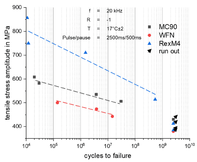
Liesegang[1A] tested the horns made of Ferro-Titanit type WFN, CPM Rex M4, and MC90 steels. These were used for ultrasonic seam welding of Ti-6Al-4V at 20 kHz (figure 13). Liesegang described these materials (p.8) —
- Ferro-Titanit WFN. Ferrotitanit WFN is already used commercially as a sonotrode material. It offers a martensitic matrix reinforced by approximately 33 wt% titanium carbide. In comparison to tool steels used for sonotrodes, the wear resistance of Ferrotitanit WFN seems to be higher [45]. Relatively low mass density and high mechanical stiffness are also promising properties for applications as an oscillating tool. However, its machinability is challenging and the material is comparatively expensive [44].
- CPM Rex M4. CPM RexM4 is a high-speed tool steel, typically used metal drilling. Compared to the commercially used sonotrode tool steel CPM 10V, the wear resistance of CPM RexM4 is lower, according to the manufacturer?s data sheet [46]. However, Rex M4 was selected because of its high impact strength in comparison to other tool steels [43].
- BÖHLER MC90 INTERMET. MC90 Intermet is a FeCoMo-alloy developed particularly for the machining of titanium alloys [42]. Hardness and wear behaviour in contact with titanium, as well as mechanical strength, are promising properties as a candidate for robust sonotrodes.
|
|
|
Liesegang's tables 5 and 6 (condensed here) show the relevant material properties.
|
||||||||||||||||||||||||||||||||
|
Table notes —
- HRC = hardness on the Rockwell C scale.
- The thin-wire wave speeds are calculated values.
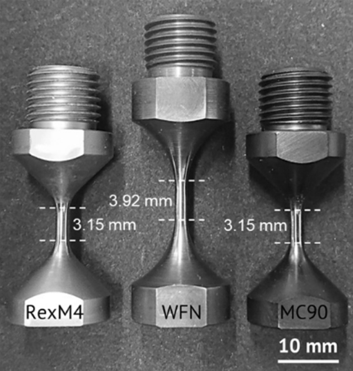
- Ferro-Titanit's thin-wire wave speed is about 30% higher than the other two steels. This means that a horn's tuned length will be correspondingly longer. This is illustrated in figure 14 for the 20 kHz fatigue test specimens. (Note that all of the lengths are quite short due to the extreme area reductions at the nodal midsections.)
- The fatigue strengths (figure 15) are taken at 2.5e9 cycles where run-outs have occurred. However, the data are limited so the true fatigue strengths may differ.
- The diameters of the test specimens are small. Large resonators may have greater possibilities for material defects so the true fatigue strengths may be lower. See Ferro-Titanit WFN.
- Fatigue strains are calculated values.
|
|
|
|
|
|
Note that the fatigue strains of table 9 are all significantly lower than the maximum recommended strain for Ti-6Al-4V (~0.0032). Thus, if high strains (amplitudes) are required then Ti-6Al-4V with a wear coating might be considered.
Unless otherwise noted, the following welding results are from Liesegang[1A].
Welding results — MC90
Of the three tested materials, MC90 achieved the best weld strengths (p. 14). Liesegang (p. 15) notes —
"In comparison to commercially applied sonotrode materials, the performance of MC90 is outstanding. Displacement amplitudes above 48 m were applied for more than 108 loading cycles during the welding of Ti6Al4V to CFRP without failure and without pronounced wear [14]. The sonotrode was used for a cumulative welding seam length of 40 m corresponding to approximately 3 x 10⁸ loading cycles. A continuous decrease in joint [weld] quality over tool's longevity was not detected during the study."
Although MC90 performed well for ultrasonic welding of titanium, Bloss[1] found that welding performance is affected by material compatibility between the horn-tip and the workpiece. Thus, it is not known how MC90 would fare when welding other materials.
Welding results — CPM Rex M4
The weld strengths were "exceptionally low" due to very pronounced tip wear (p. 14). "After a cumulated welding seam length of 1 m, the height of the RexM4 sonotrode tip profile was reduced by approximately 30%, whereas the sonotrode tips of WFN and MC90 did not show significant abrasion."
Welding results — Ferro-Titinat WFN
Ferro-Titinat WFN horns failed by fatigue during welding. Fatigue occurred, in part, because the Ferro-Titinat has higher Young's modulus than the other materials, resulting in 13% higher stress for the same amplitude (Liesegang's figure 11). Liesegang also suggests that the fatigue failures may have been due to "enhanced mechanical stress" at the TiC clusters (the sites of fatigue crack initiation). Based on these failures Liesegang assumed fatigue strength of 350 MPa was probably too high (p. 15). However, until the fatigue failures, Ferro-Titinat WFN gave similar weld strengths to MC90 (p. 15). Thus, Liesegang suggested that Ferro-Titinat WFN might be suitable if the horn could be redesigned for reduced stress (p. 16).
See Foller[1A] for Ferro-Titinat properties. Note —
- There are several grades of Ferro-Titinat, each of which has slightly different properties.
- Foller's wave speeds (his table 2) were determined the the ultrasonic pulse-echo technique. These are the dilatational wave speeds. These are higher than the thin-wire wave speeds and should not be used for design purposes. However, the other material properties in Foller's table 2 are valid.
Heat treatment
Except as specifically recommended above, see Bryson[1] for suggested conventional heat treatments (without consideration of ultrasonic requirements). Consult the material manufacturer or your heat treater who may have additional recommendations.
Effect on frequency
When a steel resonator is heat treated, its resonant frequency often changes. This must be considered when tuning prior to heat treatment so that the final frequency is correct.
Liesegang[1A] (p. 13) reported the following —
|
||||||||||||
|
Liesegang noted that Ferro-Titanit WFN is 33% (by weight) ceramic phase which is unaffected by heat treatment; hence, Ferro-Titanit WFN has a smaller frequency drop compared to the two other materials.
Culp[0] reports approximately 200 Hz frequency drop after heat treating D2 tool steel.