Steel
Contents
- Material selection
- Loss
- Effect of grain size
- Known steels
- AISI D2 tool steel
- AISI M2 tool steel
- CPM 9V tool steel
- CPM 10V tool steel
- Topic
- Topic
- Figures
- Figure 2. Figure title
- Tables
- Table 1. Table title
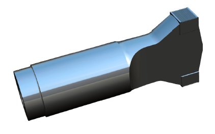
Steels are used for ultrasonic resonators when wear resistance and/or impact resistance are required. For example, they have been used in for metal welding horns (where the welding tip surface is integral to the horn — figure 1) and for horns used for insertion.
|
|
|
Material selection
Unlike titanium and aluminum, selecting an appropriate steel is complicated by several factors.
- There are thousands of different steels. Some of these have just slightly different alloy compositions but with big impact on performance.
- For heat-treatable steels there are many heat-treat variables that affect performance, for example the temperatures and durations (for preheating, heat treating, quenching, tempering), the surrounding media (air, inert gas, salts), etc. These may vary even for a specific steel, depending on the desired final properties.
- Although steels work well at relatively low strains, the loss can increase dramatically at higher strains (see figure 2). Conventional (handbook) property listings don't specify loss properties because 1) loss isn't important for conventional (non-ultrasonic) applications, 2) loss is not a fixed value but varies with the strain, and 3) loss depends on the heat treatment. Instead, loss must be determined by actual ultrasonic tests for each material and heat treatment at the expected strain levels. When attempting to achieve low loss, however, other desired properties such as wear and notch sensitivity (e.g., for threads) must also be considered.
Loss
Figure 2 shows the loss for a number of materials, including several steels. (This data, from Aeroprojects 1969, was conveyed to Culp (0) by Maropis (0).) The experimental setup is shown in figure 3. The loss was determined from the increase in temperature of water that flowed through the center of a highly stressed 15 kHz horn. Note that the losses are only valid for the particular frequency and sample shape. However, comparisons among the various materials are still valid. Table 1 shows the best determination of the hand-written notes from figure 2.
Notes —
- All steels are more lossy than Ti-6Al-4V and many are substantially more lossy.
- For 440-C steel, the wave speed decreases from 5350 m/sec to 5200 m/sec (-2.8%) as its condition changes from annealed to full hard. D2 exhibits a similar trend.
|
|
|

|
|
|

Effect of grain size
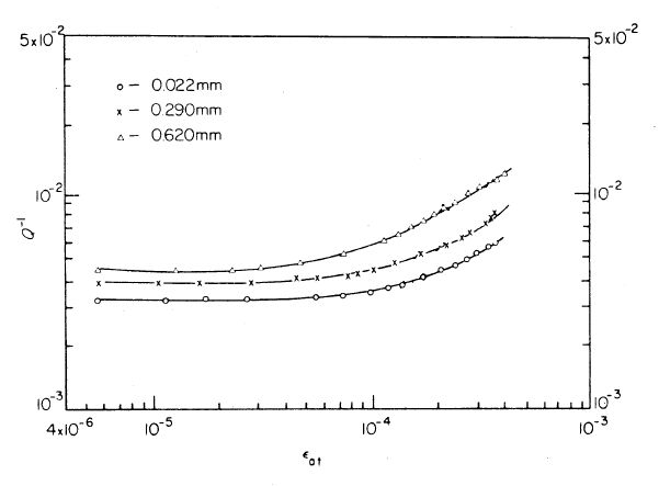
Puskar (1) tested a low carbon unalloyed steel at 23 kHz to determine the internal friction Q-1. (Note — loss varies directly with the internal friction which is the reciprocal of the quality factor Q.) The results are shown in figure 4 where the horizontal axis is the total strain amplitude \( \epsilon_{at} \). (It is believed that this is the peak strain rather than the peak-to-peak strain although this is not explicitly stated.)
As the grain size is reduced (likely due to the heat treatment process) the internal friction is also reduced. It is likely that there is some point at which further reduction in grain size does not result in further reduction in internal friction. However, this cannot be deduced from the given data.
Also, there is a critical strain \( \epsilon_{c} \) at which the internal friction starts to increase (i.e., the curves trend upward). This critical strain depends on the grain size. For example, for a grain size of 0.620 mm \( \epsilon_{c} \) is 7.3e-5 whereas for a grain size of 0.022 mm this increases to 1.3e-4. Thus, considering only the effect of loss, this fine-grained material could be driven at substantially higher amplitudes than the same coarse-grained material. The same is likely true for other steels.
|
|
|
Known steels
The following steels have been used in some manner for ultrasonic resonators. The comparative merits of these steels are not well known.
|
||||||||||||||||||||||||||||||||||||||||||||||||||||||||||||||||||||||||||||||||||||||||||||||||||
|
Table notes —
- The thin-wire wave speed is a calculated value.
- Data that are measured or calculated from ultrasonic tests are in bold type. Except as noted, these are from Culp (0). Corresponding nominal "handbook" data (typically from manufacturer's data or matweb.com) are in parentheses.
- Unless otherwise stated, all properties are at room temperature.
Table references —
- FX Temper 2 tool steel —
Poisson's ratio was measured with tensile tests on three samples (25.4 mm square).
The density was measured in the laboratory.
- Young's modulus was measured with a 40 kHz ultrasonic full-wave/half-wave test (one sample). The test sample was Ø19.1 mm.
- Young's modulus was calibrated from FEA of a 40 kHz 2-slot bar horn (one sample each).
- Young's modulus was calibrated from FEA of a 40 kHz unslotted flatted-cylindrical horn.
- Al-Sarrif (1) — 20.8 kHz metal welding horn (FEA calibrated); 20 microns p-p (p. 68); 5 microns p-p input. The integrated welding tip was hardened to HRC 55-60 (p. 54); it is not known if this applied only to the welding tip or to the entire horn.
- Stanasel (1) — 20 kHz metal welding horn (figure 1) for welding cables for the automotive industry, FEA analysis. Stanasel gives partial horn dimensions.
Notes —
- Except as specifically recommended below, see Bryson (1) for suggested conventional heat treatments (without consideration of ultrasonic requirements). Consult your heat treater who may have additional recommendations.
- Unless otherwise stated, the "Characteristics" below are from the manufacturer's data or, secondarily, from matweb.com.
AISI D2 tool steel
Characteristics — An air-hardening, high carbon, high chromium tool steel, heat treatable to HRC 60-62. It has excellent abrasion resistance due to a large volume of carbides in the microstructure.
Applications — Ultrasonic metal welding tips, plastics sealing horns, inserting horns.
AISI M2 tool steel
Characteristics — A tungsten-molybdenum high speed tool steel with excellent combination of wear resistance, toughness and hot hardness.
Applications — Ultrasonic metal welding horns.
CPM 9V tool steel
CPM refers to the Crucible Particle Metallurgy process (Crucible Industries).
Characteristics — A high vanadium tool steel with high wear resistance and good toughness. It is a modification of CPM 10V with lower carbon and vanadium to improve toughness, although its wear resistance is somewhat lower.
Heat treatment — HRC 54-56 (suggested for best combination of toughness and wear resistance).
Applications — Ultrasonic atomization of solder.
CPM 10V tool steel
CPM refers to the Crucible Particle Metallurgy process (Crucible Industries).
Characteristics — A high vanadium tool steel with high wear resistance and good toughness.
Heat treatment — HRC 60 (suggested for best combination of toughness and wear resistance).
Vertex
Characteristics — "TLS Vertex tool steel is a versatile, high-chromium, air-hardening tool steel that is characterized by a relatively high attainable hardness and numerous, chromium-rich alloy carbides in the microstructure. These carbides provide good resistance to wear from sliding contact with other metals and abrasive materials. The primary alloy carbides in Vertex are smaller than the large chromium-rich alloy carbides which are characteristic of D2 tool steel. These smaller carbides result in better impact toughness and superior fatigue properties compared to D2.
The molybdenum addition in Vertex enhances the hardness of the alloy carbides, and more significantly, provides superior secondary hardening response compared to D2. Therefore, unlike D2, Vertex can be tempered at higher tempering temperatures yet still attain a hardness in excess of 60 Rockwell C. Because of the higher secondary hardness, Vertex exhibits superior wear resistance compared to D2 tempered at the higher tempering temperatures, as well as the superior toughness that is the result of the high-temperature tempering." (Vertex data sheet)
Originally manufactured by Timken Latrobe Steel; now Latrobe Specialty Steels Co.
Heat treatment (suggested by Latrobe). Final hardness should be ~HRC 56.
- Preheating. Preheat at a rate not exceeding 400 °F/hr (220 °C/hr) to 1150 - 1250 °F (621 -677 °C), equalize, then heat to 1400 - 1450 °F (760 - 788 °C).
- Austenitizing. Heat slowly from preheat. Furnace or Salt: austenitize at 1850 °F (1010 °C)
- Quenching. Air or pressurized gas. Cool to 150 - 125 °F (66 - 51 °C).
- Tempering. Temper immediately after quenching. Heat to 1050 °F (565 °C). Hold at temperature for 1 hour per inch of thickness (2 hours minimum), then air cool to ambient temperature and repeat.
FX Temper 2
Characteristics — "A moderate level of alloys nickel (Ni .80%), chromium (Cr 1.15%) and molybdenum (Mo .5%) provides this die steel with a good balance between fracture toughness and wear resistance at the widely used Temper 2 hardness (38-42 HRC)."
Manufactured by Finkl Steel. See data sheet.
Applications — Ultrasonic atomization of solder.
AISI 630 (17Cr-4Ni; 17-4 PH) stainless steel
PH refers to precipitation hardening.
Characteristics — A martensitic precipitation/age-hardening stainless steel offering high strength and hardness along with excellent corrosion resistance.
Applications — Ultrasonic dental tips.
Notch sensitivity
A desirable property of acoustic materials is that they should have low fatigue notch sensitivity (i.e., the endurance strength with a notch should be be nearly equal to the same material without a notch). This is important, for example, in fatigue of threads.
Two similar tests that determine impact notch sensitivity are the Charpy and Izod. In these tests a heavy pendulum strikes and breaks a notched test specimen. The change in potential energy of the pendulum (before and after the strike) indicates the impact notch sensitivity. Unfortunately, however, there appears to be little or no correlation between the impact notch sensitivity and fatigue notch sensitivity. As Yin (1) (p. 12) relates, "It is generally believed that hard steels are more notch-sensitive than soft steels either in a fatigue test, a static tension test, or an impact test. Some test data have indicated that the stronger the steel the lower is the Charpy impact value and the greater the fatigue notch-sensitivity; hence, one might infer the possibility of a relation between impact values and fatigue notch-sensitivity. However, no direct correlation between these two types of test has ever been reported and some contrary evidence indicating that there is no reason to expect a correlation has been presented".
Threads
Steel horns are known to fail in the threads. This is likely due to the notch sensitivity after heat treatment. The following remedies have been suggested or tried.
- Don't bottom the stud. A bottomed stud places a tensile stress on the threads which reduces fatigue life.
- Use a titanium stud. After steel horns have been used for some time, the steel studs show fretting on the thread flanks. Since titanium has half the modulus of steel it may be able to deform under ultrasonic stress without fretting.
- Increase the horn's gain. This will reduce the ultrasonic stress in the threads.
- Use an integral stud. Rather than having a separate stud, the stud is machined as an integral part of the horn. Then the thread form can be closely controlled.
- Use a different horn material. For example, if wear resistance is needed then try an aluminum or titanium horn with a wear-surface (e.g., chrome, D-gun, carbide). (If impact resistance is needed then a relatively thin coating like chrome or D-gun might not be suitable.)