Notes
Contents
Disclaimer
The information on this site is advisory. It is provided without guarantee of any kind.
Content
This site attempts to provide a central resource for the design of ultrasonic resonators. However, it is neither comprehensive nor is it the last word.
- Consult the Contents to find a particular topic.
- A topic is released when it contains sufficient information to be useful. Thus, a particular topic may be incomplete. Please contact the site to see if additional information may be available.
- If you are unsure of the meaning of a term, please consult the Glossary.
- Unless otherwise specified, all resonators are 20 kHz designs. However, all dimensions and mechanical performances can be linearly scaled to other operating frequencies. (Note that the effect of loads, where considered, may not necessarily scale linearly to other frequencies.)
Where possible, the dimensions of 20 kHz "standard" designs have been chosen so that they scale nicely to other common frequencies (15 kHz, 30 kHz, 35 kHz, and 40 kHz). This avoids some awkward dimensions. For example, for a 20 kHz cylindrical horn, a face diameter of 126 mm scales nicely whereas a diameter of 125 mm does not. (Note: not all dimensions can be chosen to scale nicely, especially to 35 kHz.) - When an equation shows a multiplication operation, the multiplication sign "x" (or "*") is not shown. However, adjacent multiplication factors will always be separated by at least a space in order to distinguish the individual factors. For example, Newton's second law of motion would be shown as \( F = m \, \ddot{u} \) rather than \( F = m\ddot{u} \).
- Unless otherwise stated:
- For experimental tests, all performance data and tuning rates include a transducer that drives the resonator.
- For finite element analysis, the transducer is not included (i.e., only the resonator is analyzed).
- All systems are linear.
- All stress values are von Mises.
- All materials are assumed to be isotropic and homogeneous.
- All aluminum resonators are made from Al 7075-T6.
- All titanium resonators are made from Ti-6Al-4V.
- All word processing documents and spreadsheets are in .od* (open document) format, viewable with OpenOffice or LibreOffice (free office suites).
- Various vendors and manufacturers are mentioned. However, such mention does not imply endorsement.
- Various individuals and companies have graciously provided images to this site for which acknowledgment has been given. However, such acknowledgment does not imply endorsement.
| Frequency (kHz) | Face diameter ("awkward" dimensions) |
Face diameter ("nice" dimensions) |
|---|---|---|
| 20 | 125.0 (scales awkwardly to other frequencies below) |
126.0 (scales nicely to other frequencies below) |
| 15 | 187.5 | 189.0 |
| 30 | 83.333... | 84.0 |
| 35 | 71.429... | 72.0 |
| 40 | 62.5 | 63.0 |
Units
Primary units are metric. Secondary units are imperial.
|
||||||||||||
|
In the above table, secondary units (used only occasionally) are shown in brackets [ ].
Amplitude
Important — Amplitudes have traditionally been specified as peak-to-peak values. However, acceleration forces, stresses, and strains are determined from peak amplitudes, rather than peak-to-peak. Thus, peak amplitudes will be used on this site (with a few legacy exceptions). For text where there may be any confusion, the amplitude will be written as "microns_peak". In equations, the amplitude will generally be written simply as \( U \) where peak amplitude is implied.
Drawings
See here.
Finite element analysis (FEA)
Orientation
Resonators are generally shown with the output face pointed upward. This orientation has been chosen because the face amplitude distribution is often most important for the application. Drawings use this same orientation.
Colors
 |
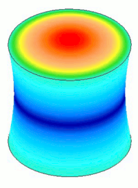
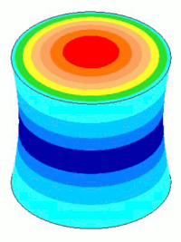
FEA colors show the relative values of amplitude and stress — hot colors such as red indicate high values whereas cool colors such as blue indicate low values. Unless otherwise indicated, the colors do not indicate any actual values. Hence, the colors generally can't be compared between different resonators. For example, two horns may both show areas of "red" stress. However, these red areas only indicate where the stress is high — they do not indicate that the two horns have equally high stresses ; in fact, one horn could have substantially higher stress than the other. |
For actual resonators the amplitudes and stresses vary in a continuous manner (i.e., they don't make sudden stepped jumps). This is shown in the left image below. However, in order to clearly distinguish different performance regions, the FEA models are shown with striated colors (the right image below).
|
||||||||||
|
During animation each color remains constant at the same value that it originally had at maximum displacement.
Displaced scale
The vibration displacements in the images are greatly exaggerated in order to be discernable.
Site
- Internet Explorer may work but is not supported.
- Links.
- Links that access other pages of this site are displayed as link.
- Because this site is under early development, many topics may have little or no information. These links are displayed as No info on this link. (If you need further information (or if you just need clarification about a particular topic), please contact us.)
- Links to glossary terms are displayed as term.
- Links to external web pages that open in a new tab or window are displayed as link.
- If this site is viewed on a low resolution device such as a small tablet, then some items (tree menus, equations) may not display properly. If a tablet or similar device is required then try viewing in landscape mode.
- In order for the Google translation to work, an internet connection must be established.
- Equations —
- After a page is initially displayed, any equations will require additional time to display properly. The time will depend on the number and complexity of the equations. The progress will be displayed at the bottom of the page as Typesetting Math. Don't refresh or scroll the page until the typesetting has finished.
- For equations that are displayed in italics, CTRL+click on the equation will magnify it by 2x. Clicking again on the equation will restore normal magnification. (Note: when hovering above the equation, the cursor shape does not change to indicate that the equation is clickable.)
- Equations will not display properly without an internet connection.
- For A4 or letter sized paper, pages print best with 12 mm margins all around. To avoid clipping at the right margin, the sum of the left and right margins should be less than 50 mm.
Troubleshooting
- Images are distorted. This may be caused by your browser.
Test image — The following image is a circle. If it appears as an ellipse then your browser is not displaying images correctly.
- Equations don't display. Instead of an equation you may just see LaTeX formatting text. In order for the LaTeX to display correctly, your browser must allow javascripts to run. Check your browser configuration options.
Test equation — If your browser is correctly configured then the following should display as E = m c2 rather than LaTeX formatting text —
\begin{equation} E = m \, c^{2} \end{equation}
- Equation numbers don't display. Generally, each equation should be numbered. If not, try refreshing the page.
- The Contents and Glossary tree menus do not display/operate correctly. Your browser must allow javascripts to run. Check your browser configuration options.
Revisions
See here.
Privacy
This site does not collect any user information and does not use cookies.

