Spool Horns - Under Construction
Contents
- Figures
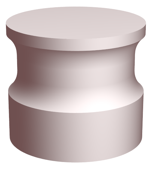
- Figure 1a. Standard spool horn
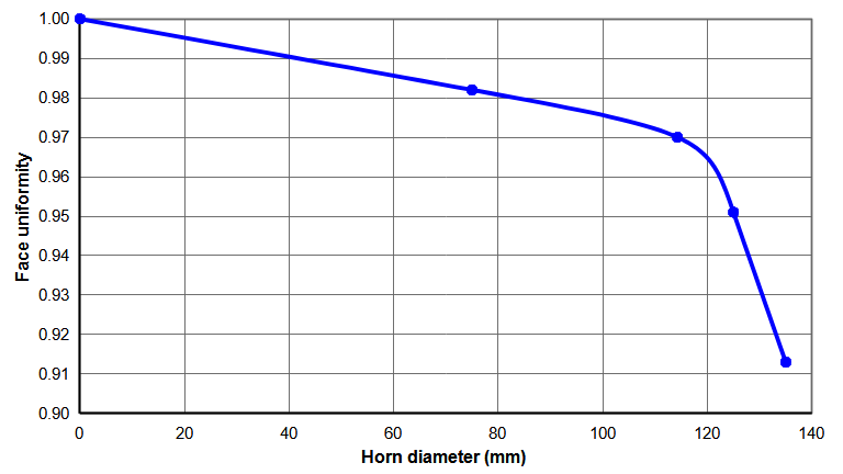
- Figure 10. Achievable face uniformity
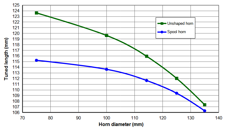
- Figure 20. Tuned lengths for 20kHz Al 7075-T6 unslotted cylindrical horns
- Figure 30. Effect of steel stud on face amplitudes for 20kHz Al 7075-T6 Ø135 spool horn
- Figure 31. Effect of steel stud on gain for 20kHz Al 7075-T6 Ø135 spool horn
- Figure 40. Effect of Poisson's ratio on face amplitudes for 20kHz Al 7075-T6 Ø125 spool horn
- Figure 41. Effect of Poisson's ratio on face amplitudes for 20kHz Al 7075-T6 Ø110 spool horn
The following discusses the procedure for improving the uniformity of large diameter unslotted cylindrical horns.
Unless otherwise specified —
- References to "amplitude" and "uniformity" will mean those on the horn’s face.
- Horns are assumed to be flat faced (i.e., no face contour or cavity).
- The designs and performances are based on 7075-T6 aluminum with a wave speed of approximately 5005 m/sec and a Poisson's ratio of 0.33. These should apply approximately to materials with similar properties (e.g., titanium, many steels) but some adjustments (particularly the undercut diameter) may be needed for optimum performance. However, materials with significantly different wave speeds (copper alloys, AlBeMet) or significantly different Poisson's ratios (AlBeMet, some steels) must be optimized separately.
- The suggested dimensions apply to 20 kHz horns. These dimensions can be scaled to other frequencies.
- All dimensions are approximate and should be adjusted as needed for the particular horn and/or application.
- All amplitudes are referenced to 1.0 axial at the center of the horn face.
Unshaped cylindrical horns
For unshaped cylindrical horns, Poisson's coupling gives a face amplitude that is highest at the center of the face and lowest at the periphery. (See details.) Figure 1 shows the face amplitude distribution for a Ø135 mm horn.
Figure 2 shows how the face amplitude uniformity varies with the horn diameter. For horns with diameters up to 60 mm the uniformity is greater than 0.9 (90%). For larger horns the uniformity falls off quickly. For a Ø135 mm horn the uniformity is only about 0.25. Such nonuniformity can cause problems in performing the application.
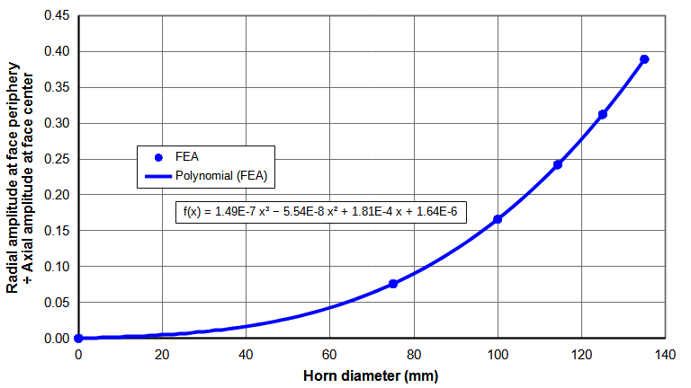
Figure 3 shows the radial amplitude at the face periphery. Up to Ø125 mm the radial amplitude is less than 2% of the axial amplitude at the center of the horn's face. Above Ø130 mm the radial amplitude increases quickly. At even larger diameters the radial amplitude predominates and the horn acts more like a radially vibrating disk.
Spool horns
In order to improve the face axial uniformity, a spool shape (somewhat like a spool of thread) is cut into the periphery of the horn behind the face.
|
|
| Figure 1. Standard spool horn |
|
The spool undercut increases the amplitude at the face periphery and in areas adjacent to the periphery by allowing the flange material to "flap". Generally, the optimum undercut is achieved when the axial amplitude at the face periphery equals the amplitude at the center of the face. In between these two locations the amplitude will be somewhat lower because the "flapping" is not as effective in this region.
Characteristics
Face cavity
Spool horns (especially the larger diameters) with a substantial face cavity do not retain good uniformity. (A small cavity like an axial hole for cooling or vacuum may be acceptable.) If a substantial face cavity is required then a slotted cylindrical horn should be used instead.
Maximum diameter
The largest reasonable horn diameter is about 135 mm at 20 kHz. This is limited by requirements for amplitude uniformity, radial amplitude, and an adjacent nonaxial resonance.
Amplitude uniformity
Figure 10 shows the achievable face uniformity for spool horns that are designed according to figure 4. The achievable face uniformity decreases sharply for horns above about Ø120 mm.
|
|
| Figure 10. Achievable face uniformity |
|
Radial amplitude
At Ø 135mm the radial amplitude is about 39% of the axial amplitude; above this diameter the radial amplitude increases quickly (figure 6), which may affect the application (e.g., scuffing of the plastic part). This radial amplitude is high because the undercut makes the face appear like a radially vibrating disk.
|
|
| Figure 6. Standard spool horn |
|
Adjacent nonaxial resonance
Above Ø135 mm there is a symmetric nonaxial resonance that can adversely affect the axial resonance. Figure 7 shows this mode at 21213 Hz for a Ø135 mm spool horn.
Excluded diameters
Horns with diameters near 100 mm have an asymmetric shear resonance near 20 kHz. This resonance has a diametral node across the face and stud surface (figures 8 and 9). When this asymmetric resonance is close to the axial resonance it causes asymmetric amplitudes on the face and stud surfaces. Spool horns with diameters less than 90 mm or greater than 110 mm appear to be relatively unaffected by this resonance; spool horns between these diameters must be carefully evaluated to make sure that any asymmetric face amplitudes will not affect the application or cause other problems (e.g., heating of the horn-booster joint or heating of the transducer).
Gain
Spool horns have a gain near 1.0, even though the undercut (reduced mass forward of the node) would seem to indicate a higher gain. The gain decreases as the horn diameter increases (figure 11). (Note: as is common practice, the gain is measured at the center of the horn's face.)
Stress
The highest stress occurs in the undercut radius that is near the node. The stress for all of the Al 7075‑T6 spool horns up to Ø135 mm ranges from 2.34 – 2.48 MPa/micron_peak output [340 – 360 psi]. These horns have proven reliable at output amplitudes of 25 microns_peak (59 - 62 MPa). Since Al 7075-T6 has a fatigue strength of 130 - 140 MPa, it is likely that these spool horns would be reliable at significantly higher amplitudes.
Design procedure
Refer to the following —
|
|
| Figure 20. Tuned lengths for 20kHz Al 7075-T6 unslotted cylindrical horns |
|
- Choose the horn material.
- If possible, use aluminum (e.g., Al 7075‑T6) which is relatively inexpensive and is easy to machine. If needed, wear resistance can be improved by plating the face (e.g., hard chrome). (Caution: some platings can reduce fatigue life.)
- Titanium (e.g., Ti-6Al-4V) can be used where wear or impact problems can't be resolved with aluminum.
Fatigue failures of aluminum spool horns are rare so the fatigue advantage of titanium over aluminum is usually not a consideration.
Note that large diameter titanium spool horns may be difficult for the power supply to start, especially when driven with a high gain booster. Power consumption will also be high. For example, a Ø135 mm titanium spool horn with approximately 45 microns output draws in excess of 400 watts in air (Culp[0]). Thus, large diameter titanium spool horns are not recommended.
- Specify the dimensions.
- Flange length. A 12 mm flange works well. A larger flange will shift the point of lowest face amplitude closer to the centerline and can increase the uniformity slightly. However, the undercut will have to be deeper to compensate, resulting in higher stress.
- Undercut radius. A 25 mm radius works well. A smaller radius will increase the amplitude at the face periphery. Then the undercut diameter will have to be reduced, resulting in somewhat lower uniformity.
- Undercut diameter. Make the undercut diameter approximately 85.5% of the horn diameter. For all horn sizes this will give approximately the best face uniformity. (Some adjustment may be needed to compensate for the stud (below) and the material. To be safe, start with a shallower undercut and then reduce the undercut diameter in order to achieve the optimum result. Large diameter horns are very sensitive to the undercut diameter (i.e., small changes in this diameter will significantly affect the face uniformity). For example, for a Ø135 mm spool horn, reducing the undercut diameter from 86.0% to 85.3% increases the edge axial amplitude from 86% to 101% of the center axial amplitude. This sensitivity is compounded by the effect of Poisson's ratio (below).
- Rear shoulder location. The rear shoulder is where the rear radius intersects the rear major diameter. Set the distance from the horn face to the shoulder as 57% of the tuned length of the unshaped cylindrical horn (see figure 20). This gives the highest gain (although the gain is only somewhat affected by the shoulder location).
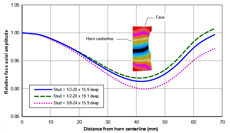
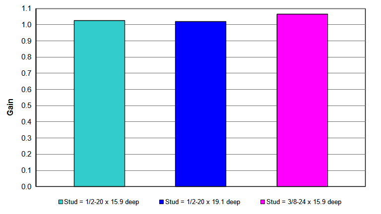
- Stud. Up to a stud diameter of approximately 13 mm, the face amplitude and gain are only somewhat affected by the stud dimensions. For example, see figures 30 and 31 for a Ø135 mm spool horn. Smaller spool horns show even less effect. (The amplitudes will also be affected by the stud material — steel versus titanium.)
|
|
Figure 30. Effect of steel stud on face amplitudes
for 20kHz Al 7075-T6 Ø135 spool horns |
|
|
|
| Figure 31. Effect of steel stud on gain for 20kHz Al 7075-T6 Ø135 spool horn |
|
- Tuned length. With the dimensions of figure 4, the tuned lengths are shown in figure 20. Because the flange length is fixed, the horn must be tuned from the stud surface. For all horns, the tuning rate will be about 120 Hz/mm with an attached transducer. (The spool horn will always tune shorter than an unshaped horn of the same diameter. Therefore, the pretuned length of figure 20 can just be set to the length of an unshaped horn of the same diameter.)
Effect of Poisson's ratio
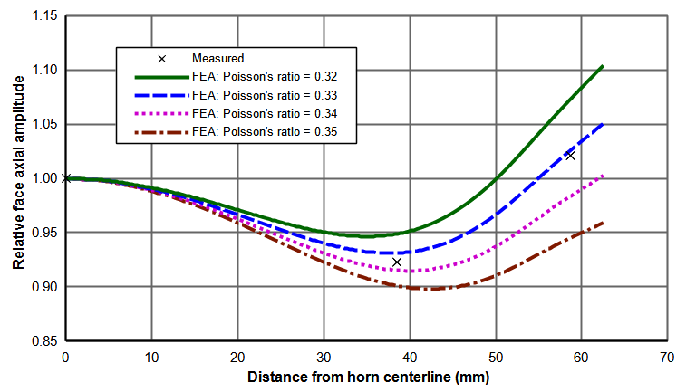
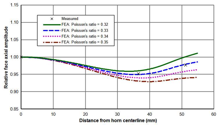
When designing spool horns with FEA, the value of Poisson's ratio can have a significant effect on the resulting amplitude distribution across the horn's face. Figure 40 shows this effect for a Ø125 mm Al 7075‑T6 spool horn. As Poisson's ratio varies from 0.32 to 0.35 the amplitude at the periphery changes by about 15%. This effect decreases as the horn diameter decreases, as shown in figure 41 for a Ø110 mm Al 7075‑T6 spool horn where the amplitude at the periphery varies by about 7% between the lowest and highest Poisson's ratios. Details ...
|
|
Figure 40. Effect of Poisson's ratio on face amplitudes
for 20kHz Al 7075-T6 Ø125 spool horns |
|
|
|
Figure 41. Effect of Poisson's ratio on face amplitudes
for 20kHz Al 7075-T6 Ø110 spool horns |
|