Amplitude uniformity — basic concepts
Contents
- Definition
- Need for uniform horns
- Cause of nonuniformity
- Also see — Uniformity and asymmetry calculations
- Figures
This section will consider some general aspects of amplitude uniformity.
Definition
Amplitude uniformity (generally just "uniformity") is a measure of how much the amplitude varies over a given surface.
Need for uniform horns
Consider an ultrasonic plastic welding application in which two very compliant strips of uniform thickness are to be welded together. To get uniform welding along the joint, an equal amount of ultrasonic energy must be delivered to each point along the weld joint. Since energy delivery is a function of the horn amplitude, equal energy delivery requires equal horn amplitude at each location where the horn contacts the strip. If the horn face amplitude is not uniform, then some section of the joint may be underwelded while other sections are overwelded. Thus, the uniformity of horn face amplitude is an important consideration in horn design. (Note: for the present this discussion will be confined to horn face uniformity. However, amplitude uniformity on the stud surface is also important as will be discussed later.)
The precise uniformity requirements will depend on the application. Rigid plastics are somewhat tolerant of nonuniform horns. This is because the stiff plastic can transmit ultrasonic energy to adjacent joint areas, which results in a more uniform energy distribution along the joint. Also, rigid plastics permit joints (energy directors) that can sometimes compensate for inadequate horn uniformity. Finally, many plastic welding applications require only a certain average weld strength, so that some over-welding and under-welding along the joint is permissible.
There are certain circumstances where high uniformity is needed:
- Hermetic seals. A hermetic seal requires adequate joint strength along its entire perimeter. A uniform horn improves the probability of success.
- Thin-film applications. When welding thin-films (such as synthetic fabrics), the film is too flexible to transmit ultrasonic energy to adjacent areas. Also, the film cannot be designed with an energy director. Thus, the entire responsibility for a proper weld lies with the horn (assumng that the fixture has been properly designed)..
- Composite horns. A composite horn consists of a mother horn to which tip horns are attached. If the mother horn does not have uniform face amplitude, then the tip horns will flex. This can cause fatigue failure of the tip horns, joint problems between the tip and mother horn, flexure failure of the converter, problems with spurious resonances, and poor welding.
- High amplitude joints. When a joint operates at high amplitude, the joint may deteriorate due to fretting at the contact interface. This leads to heating and higher power loss; the joint may seize if the problem is severe. This problem will be worse if the joint has high amplitude and if the horn has poor uniformity across the joint.
Cause of nonuniformity
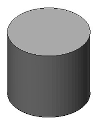
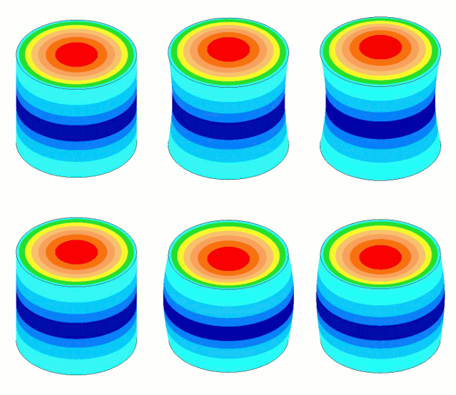
Amplitude nonuniformity is caused by Poisson coupling so that as the resonator vibrates longitudinally it "breathes" laterally. However, this breathing is not uniform along the length of resonator — i.e., the amount of breathing will be greatest where the strain (stress) is highest. Thus, for an unshaped resonator the breathing will be highest at the node and lowest (near zero) at the output and input surfaces. This nonuniform breathing distribution leads to nonuniform face amplitude. This effect is shown in figure 1.
|
|||||||||||||||
|
The amount of breathing depends three factors.
- Poisson's ratio. Materials with a high Poisson's ratio breathe more and hence have reduced amplitude uniformity.
- Thin-wire wavelength. Materials with a short wavelength (low wave speed) have greater strain at a given amplitude and, hence, greater breathing.
- Lateral dimensions. Resonators with large widths, thicknesses, or diameters will breathe more than their slimmer counterparts.
The first factor depends only on the material. The second factor depends on the material (the wave speed) and the frequency. The third factor depends on the resonator design. The second and third factors can be combined to define the slenderness of the resonator.
\begin{align} \label{eq:10201a} \textsf{Slenderness} = \frac{\textsf{Lateral dimension}}{\textsf{Thin-wire half wavelength}} \end{align}
For an unshaped resonator the lateral dimension is the diameter. Thus, when the resonator diameter equals the thin-wire half wavelength, the slenderness is 1.0.
Note that the wavelength is inversely proportional to the frequency. Thus, a resonator appears slim at 20 kHz may appear "stout" at 40 kHz if the resonator's lateral dimensions are not changed. (There is no specific slenderness value at which a resonator can be considered to be stout.)
Therefore, to reduce the breathing and improve the uniformity —
- The resonator should be slender (long wavelength and small lateral dimensions).
- The resonator material should have a low Poisson's ratio.
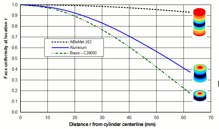
The table and graph below show these effects for 20 kHz unshaped Ø125 mm horns made of typical acoustic materials (aluminum, titanium, and steel) and two rather extreme materials (AlBeMet® 162 and brass).
|
||||||||||||||||||||||||||||||||||||||||||
|
Table notes:
- The horn is unshaped and does not have a stud.
- The following table gives some additional information for the above table. Note that generic material properties were used for aluminum, titanium, and steel.
Table 2. Supporting information for table 1 Material Young's modulus
(GPa)Density
(kg/m3 )Tuned length
at 20 kHz (mm)AlBeMet® 162 193 2100 238 Aluminum 74 2840 112 Titanium 119 4430 115 Steel (tool) 208 7670 119 Brass (C26000) 110 8525 38 - The thin-wire wave speed is calculated as \( \sqrt{\textsf{Young's modulus}/{\textsf{Density}}} \).
- The given tuned lengths are only for 20 kHz unshaped Ø125 mm horns.
- See the equation for uniformity calculation.
- The maximum radial amplitude occurs at the node. Its value is relative to the axial amplitude at the center of the horn's face.
|
|
|
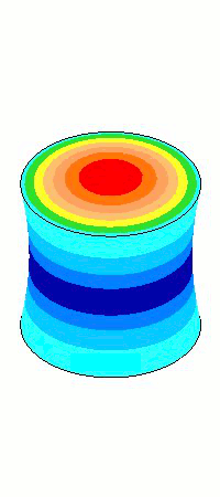
The images of the axial amplitudes in the above graph are enlarged below in figure 3. The horn with the best uniformity is that which has the fewest amplitude rings on the face. (The number of rings along the length is not significant.) In this case the AlBeMet® is clearly superior.
|
|||||||||||||||
|
From a uniformity standpoint, AlBeMet® 162 (62% aluminum, 38% beryllium) has very desirable properties - a high wave speed which gives it a long length relative to its diameter and a low Poisson's ratio; the resulting uniformity is 0.93. On the other hand, brass has rather undesirable properties - a low wave speed which gives it a short length relative to its diameter and high Poisson's ratio; the resulting uniformity is only 0.17. In fact, at this diameter brass acts more like a radially vibrating disk than an axial resonator since its radial amplitude is 47% greather than its axial amplitude.
(Although AlBeMet® 162 exhibits superior uniformity, it has at least two significant problems related to its beryllium content: 1) it is very expensive, and 2) it poses a health hazard if any of its beryllium dust is breathed during machining.)
Because their wave speeds and Poisson's ratios are similar, aluminum, titanium and steel all have generally similar (but not identical) axial uniformities and radial amplitudes.
Other resonator types
Although the above discussion was specific to unslotted cylindrical horns, the same principles apply to other resonator types (slotted cylindrical horns, bar horns, and block horns). Methods for improving uniformity will be discussed elsewhere.


