Modal interaction
Overview
When two resonances are close together they may interact. This can distort the amplitude field of the primary resonance and/or may cause the power supply to jump to the secondary (parasitic) resonance.
Example
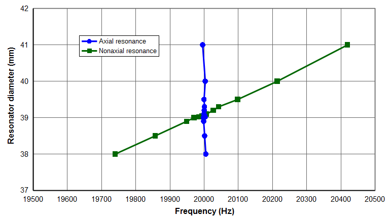
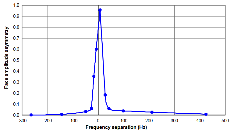
The following shows an example of modal interactions for a 20 kHz cylindrical prismatic horn (\( c_{tw} \) = 5100 m/sec; Poisson's ratio = 0.33). The horn's diamter was adjusted beetween 38 mm and 41 mm in order to affect the amount of modal interaction. The horn's length was adjusted slightly (between 126.54 mm and 126.62 mm) to maintain the axial resonance at 20 kHz. As expected, the modal interaction is greatest when the frequency separation is smallest. (Also see Amplitude asymmetry.)
|
|
| Figure 1. Frequencies for a 20 kHz \( \phi \)40 mm horn |
|
|
|
| Figure 2. Face amplitude asymmetries for a 20 kHz \( \phi \)40 mm horn |
|
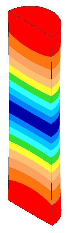
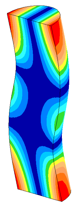
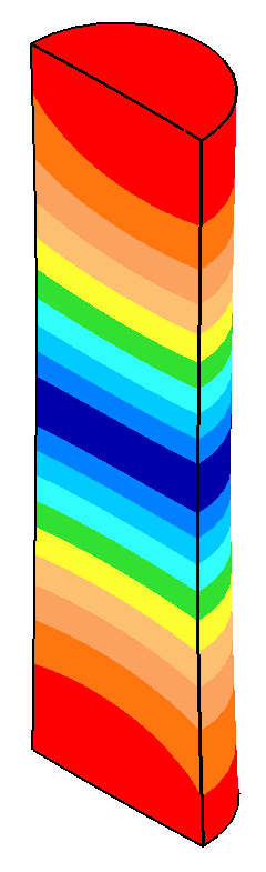
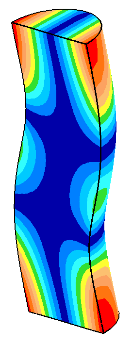
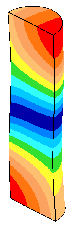
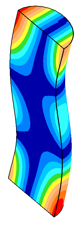
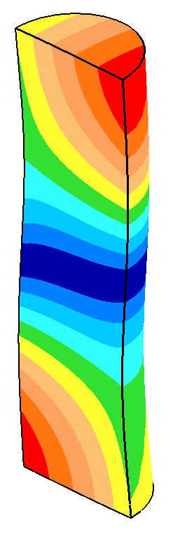
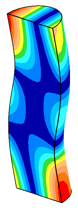
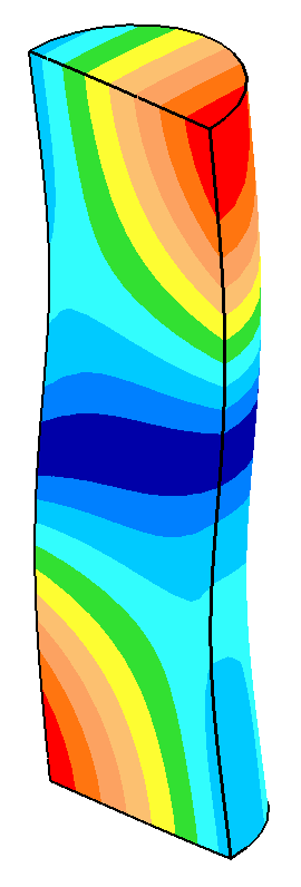
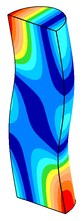
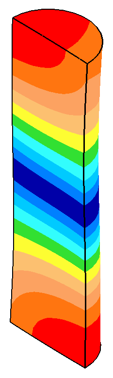
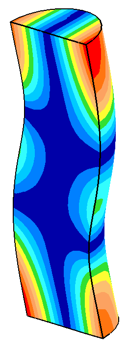
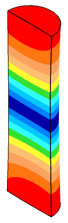
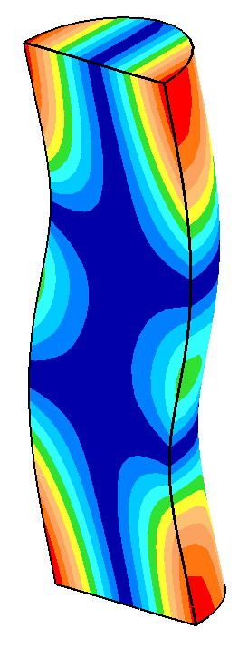
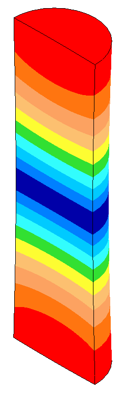
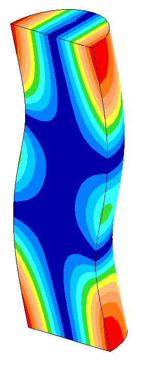
The following table shows some data from the above graphs. When the nonaxial (bending) mode is close to the axial resonance (low frequency separation), small changes in the horn's diameter cause large changes in the amplitude asymmetry. In particular, the face motion of the axial resonance starts to assume characteristics of the bending resonance. When the frequency separation is sufficiently large, the axial mode performs as if the bending mode were not present.
Table notes —
- All displacements (as represented by the image colors) are in the axial direction.
- All displacements are displayed at the same scale.
| Diameter (mm) |
Frequency
separation (Hz) |
Axial mode |
Nonaxial mode |
| 38.00 |
-265
|
|
|
20005 Hz
Asymmetry = 0.001 |
|
|
|
| 39.00 |
-27 |
|
20000 Hz
Asymmetry = 0.06 |
|
|
|
| 39.02 |
-18 |
|
19998 Hz
Asymmetry = 0.34 |
|
|
|
| 39.05 |
-12 |
|
20000 Hz
Asymmetry = 0.50 |
|
|
|
| 39.10 |
6 |
|
20000 Hz
Asymmetry = 0.96 |
|
|
|
| 39.20 |
27 |
|
20000 Hz
Asymmetry = 0.18 |
|
|
|
| 39.30 |
42 |
|
20001 Hz
Asymmetry = 0.06 |
|
|
|
| 41.00 |
424 |
|
|
19996 Hz
Asymmetry = 0.008 |
|
|
|
Suggested frequency separation
In an optimization of a 20 kHz 4.5" x 6" (114 mm x 152 mm) titanium block horn, O'Shea [1] (p. 260) specified a target frequency separation of at least 1200 Hz between the axial and nonaxial resonances. The reason for this target wasn't specified. If the reason was to avoid frequency jump then it should be noted that power supply controls have become much more sophisticated since this 1991 presentation so a narrower frequency range may be possible. In fact, horns having frequency separations of 500 Hz at 20 kHz have been successful.
Liesegang[1A], p.10 specified a frequency separation of 1000 Hz at 20 kHz.